- Details
- Category: Multi-gauge Projectors
Specto
SPECTO
For use of the Specto for Ultra Pan 8, click here
There is now lots on Specto, so a separate page is indicated. Aunt Em has had some Specto correspondence, too. The Ultra Pan 8 page also has stuff on it of more general relevance, tho' I haven't bothered to repeat it here.


This is a picture of a 9.5/16 Specto from the Picture Gallery; there was also an 8/16 model. Single-gauge 8, 9.5 and 16 machines were made, too. Today, only the 9.5 and 9/16 machines seem to be in any demand; 8 and 16 machines, often in fine condition, are more or less given away. One day I must see if it is possible to transplant the 9.5 bits from a knackered machine to a pristine 8mm one. (Colin Loffler says he has done it He was right - I have it now). My 8mm-converted-to 9.5 (by Colin Loffler) Specto performs very well; the only slight hitch I have found is that the 9.5 framing needs to be at one end of the available adjustment. This means that when I want to open the lens housing to clean the gate, I have to slack off the framing a bit before the thing will open, and re-adjust afterwards. But the light output with original lamp is excellent.
I have come across what I fear may be evidence that Spectos, too, suffer from the dreaded Mazac disease. I had a 9.5/16, converted to QI, but non-functional because on of the raised "bearings" for the mech, on the plate behind the lens holder, had partially broken away and stopped the claw mech working properly. On closer examination, it looks like this was not the first time - two others seem to have been replaced. When I dismantled it all, the gearbox was very stiff and some of the individual gears were very tight in the bearings. I tried to remove the shutter shaft, but this actually broke the entire plate in two - very Mazac. This didn't matter as it was already well past it and I was deeply suspicious that Mazac had a part to play in making some of the shafts very stiff in the bearings. Worse, one of the 800' spool arms just broke apart in me 'ands, 'onest guv. This could probably be fixed if I needed to.


I have labelled bits in pic 7; 1 is the raised "bearing" referred to above - you can see the side has broken away and it simply would not hold the shaft it was supposed to support. At 7, the same thing seems to be happening to part of the hinge. 2&3 seem to me like replacements for broken parts (held by a screw from the other side) and I have suspicions about 5&6, tho' I may be wrong. Some of these are seen closer up in the next pic.
Anyway, to return to the plot, I also had a very nice 16mm Specto 750 with, as you would expect, a 750w mains lamp and the larger-barrelled lens that appeared in some late Spectos. I managed to transplant the 9.5/16 parts to the 16mm body, tho' I had to cut off a bit of one shaft which, as it was hardened steel, was tricky. Hopefully, I now have a decent 9.5 (and 16) Specto that has probably had less use than the poor, tired old 9.5 machines one sees so often. And it's gold and shiny. Done an 8mm to 9.5 one as well, now.


There are at least 2 quite different types of front gate fixing (quite apart from the adaptable gates for dual gauge machines). There is the simple single screw top and bottom type, with a large gate cut-out to miss the claw, and the more sophisticated four-point jobbie, used with a retractable claw. The latter seems to go with the wire gate-opener shown in pic 3; the earlier type has a cam immediately next to the handle, which works on one side of the gate only. Great care is needed with gates, because the screws are small (tiny in the case of the one that holds the gate-opening lever in place) and the threads are into Mazac or something very similar - it is all too easy to strip the threads.
The more complex arrangement of the retractable claw involves a different film retainer for the sprocket - earlier ones are straight and simply ride on the sprocket itself, and so, presumably, on the film, hence perhaps the change. Incidentally, I was wrong about 2&3 ; they seem to be the holes for the retractable pin that holds the rollers above rather than on the film.
I have mentioned earlier a problem with my 8mm-converted-to-9.5 Specto that I got from Colin Loffler. To open the gate, I have found it necessary to slack off the framing screw; the adjustment for 9.5 is close to the bottom of the available travel and I can't else open the gate. Then I have to re-adjust afterwards. However, I noticed while working on the Spectos that there is a small washer, really a spacer I suppose, inserted just above the lower hinge. I've not spotted it before; it may not always be there, having gotten lost over time. And I don't know what it does, tho' it is clearly original as it matches the colour of the projector. So I have removed it from the offending projector to see if it overcomes my little problem.
Finally, I have often noticed that the Specto lower arm leaves a 9.5 900' spool too high, so that it can interfere a little with the bottom of the projected picture. This presumably relates to the 800' capacity, which was all Specto claimed. On the ones I have been working on, I have noted that there is considerable scope for lowering the arm by filing away the "elbow" on the rear of the spool arm, which contacts that lump cast into the main body to support the arm. I made sure there was still room for a 1000' 9.5 reel, as I use these a lot, but there's no point in leaving the arm higher than need be.
In the 9.5 section, under Silent to Sound, are details of Specto sound units, repeated here as page 2 of this article.
The problems with adding sound to a silent machine are many. Among them is the sheer speed of operation, 50% faster than envisaged at the design stage. One has to accept this proved no problem with the Gem mechanism. However, the Specto already had a mechanism where the claw operated twice per frame, being held back from engaging the film on the second stroke. One would expect wear if not worse. Probably the biggest problem is controlling the speed - a simple electric motor tends to gain speed as it warms up and to vary its speed with variations in load. Together with smoothing the film across the sound reader, this could significantly affect sound quality.
Associated Cine Equipments (ACE) of Erith, Kent, made add-on sound units for Gem and Specto, for both 16mm and 9.5mm, with 12 watts sound output claimed. They were sold either as complete units with projector, in a case, or separately. I have a copy of a 1950 advert. Prices were:-
Gem, complete projector 9.5 81 12 0 Sound unit only 44 2 0
16 92 10 052 10 0
Specto9.5 95 12 0 54 10 0
16 99 10 0 54 10 0
The Specto unit was designed for the standard 400ft capacity model; the lower arm remained in place, but folded down against the front of the projector. A unit to take the Educational model was available at a slightly higher price. The unit itself had a 900ft take-up; a top spool extension arm was available for 10s. 6d. I have to say that these prices look stupendously high, considering what average weekly wages must have been. A test Report on the 9.5 unit was published in the October 1959 issue of Amateur Cine World (ACW). Here is the text.
"The outstanding feature of these Sound Units is that no modification to the projector is required - an important point. There can be no doubt that the Specto is a difficult machine to convert as the motor occupies the very place where one would wish to put the soundhead. It is interesting to note, therefore, that Associated Cine Equipments have located their soundhead after the lower sprocket, which means that the film is pulled through the soundhead by the take-up reel.
Tests show that this unconventional procedure works extremely well. The sound is very good, comparing most favourably with that from other 9.5mm machines. Our critical ears detected a small amount of wow, but this would doubtless not be noticed by the average audience. Obviously, it is essential to use reels that are not bent, and take-up belts of the correct type, to maintain smooth film travel.  We tested a 9.5mm standard (100 watt model) Specto projector and Sound Unit. The unit is solidly built from aluminium castings, and the black crackle and plating match the finish of the Specto exactly. The appearance of the complete unit is unified and quite pleasing. (Note that the pictures are my 9.5/16 machine, with the longer arms cannibalised from a 16mm machine. I had to remove the lower arm; with 400 ft capacity, the arm would fold down between the motor and the sound unit - MAS).
The Sound Unit incorporates the complete soundhead and amplifier very neatly. There are no loose "extras." The Specto is simply placed on the platform of the unit. Adjustable locating bars are provided to allow for any small differences in the position of the film path on different Spectos, so that the projector can be accurately lined up with the sound head.
The soundhead
The sound head itself, located on top of the Unit, scans the film on a rotating drum in the customary fashion. The sound drum shaft, mounted in ball races, carries a solid flywheel 4.75 in. diameter and nearly 0.5 in. thick. A roller below the drum provides the necessary drag, and holds the film onto the drum. The film is guided between a flange on one side of the roller, and a flange on the opposite side of the scanning drum. A roller above the drum carries the film round to the take-up reel.
The photocell, a midget type CG-10, is fitted in a very neat plug-in holder. The cell protrudes into the hollow interior of the scanning drum, where it directly picks up the light coming through the sound track - there are no mirrors, etc., to get out of adjustment.
The optical system - the standard projected slit type - has a relatively long focus objective lens, so there is plenty of room between the optical system and the drum for the film to be threaded comfortably and easily. The 4 volt 6 amp exciter lamp is fed from the transformer with raw A.C., but due to the high amperage and high thermal capacity of the thick filament there is negligible mains hum. A neat feature is that the exciter lamp also illuminates the control panel through a plastic window.
Compact amplifier
The very compact amplifier, in which the valves are lying 'on their sides', permits the shallow construction of the part of the base on which the projector stands. Grilles above and below the valves provide ventilation. The valves, all standard International Octal types are; 6J7 first stage, followed by double triode 6SN7 amplifier and inverter respectively, and two 6V6 output valves in push-pull. The rectifier is a 5Z4. The amplifier has an output of approximately 12 watts. We obtained ample volume in a large room with the volume control in about the half way position. From this we should judge that a 250 watt model Specto and the appropriate Sound Unit would give a creditable performance in a small hall.
A socket is provided for a gramophone pick-up to be plugged into the amplifier. The pick-up socket feeds into the second stage of the amplifier. A change-over switch on the control panel permits selection of film or gram. No provision is made for balancing level and tone of the two; the pick-up would normally be balanced externally to the film. The switch for film/gram changeover is definitely a good point for the amateur showman. No tone control is provided on the amplifier, which is set at a pleasing balance for film.
A small but important refinement of the Sound Unit is that the mains are plugged only into the Unit. A plug on the Unit provides current to the Specto. A good feature is that the same three pin plugs and sockets are used on the Unit as on the Specto itself, so the Specto owner's leads will be suitable for the Unit, and the three pins permit proper earthing of the metalwork. Both switches are normally left "on", and the machine operated from the control panel of the sound unit.
The amplifier is automatically switched on when the jack on the loudspeaker lead is plugged into the amplifier. A voltage selector for 200 to 250 volts (on the model we tested) is provided on the amplifier, which, like the usual transformer model Specto, is suitable for A.C. mains only.
The loudspeaker, a 10 inch Wharfedale of 15 ohms impedance, is contained in an attractive leatherette covered wooden case, which also serves to carry the Sound Unit when not in use. The take-up arm is also carried in the case. Some 30 ft. of speaker cable is provided, and is wound around brackets in the speaker case for storage. A well-made carrying case for the Specto projector is available as an extra; this is covered in grey leatherette to match the speaker case. A monitor speaker is available for those who wish to use the machine in a separate room or operating box.
Spool arms
The Specto we used had 400 ft. spool arms with an extension piece supplied by A.C.E. fitted to the top arm to enable it to take 900 ft. reels. A machine with Specto 800/900 ft. arms would not require this. When the Specto is placed on the Sound Unit, the lower (400 ft.) spool arm of the projector is in the folded position. A lower 800/900 ft. type arm would have to be removed before placing the projector on the Sound Unit.
The lower spring belt is replaced by a small rubber belt. It is this which provides a positive drive to a double pulley on the Unit, and from there a spring belt provides the slipping drive to the take-up spindle. A special take-up arm for reels up to 900 ft. capacity is supplied with the unit, and screws to the front of the casting.
For the 16mm Units, a special 1,600 ft. lower spool arm is available. This does not take its drive from the projector, since that would no doubt place undue strain on the motor. Instead, the 1,600 ft. arm has its own induction motor drive and slipping clutch (as distinct from the better known practice of using a series wound motor with a positive to the reel but "electrical" slip). The separate motor, which takes its current from the unit, gives the best quality sound on large reels of 16mm., because it gives a smoother take-up and hence a smoother drive to the film at the soundhead.
To mask off the sound track when sound films are being shown, a simple slide-over gate mask (supplied with the Sound Unit) is fitted to the 9.5mm Specto. The mask fits behind the top screw which holds the front plate of the gate on the Specto, and is moved in or out of position with the finger after taking out the lens. We found that it tended to raise the front plate of the gate slightly, so a little care was needed when threading to slip the film into the gate without its meeting the edge of the front plate. No mask is, of course, needed on 16mm.
A nice feature is that tilting of the machine is provided by the two front feet of the Sound Unit. The Specto seems to maintain sound speed surprisingly well once the motor has been warmed up. Messrs. A.C.E can fit governors, but they do not feel that the extra cost is justified for ordinary usage. Further, they prefer the user to hold to their commendable principle that no modification should be made to the Specto.
Four models
Two models of the Sound Unit take the 9.5mm Standard and the Educational Spectos, while another two take the 16mm machines.
It will be remembered that the 16mm Specto has claws on the inside, whereas S.M.P.E. sound film normally requires the claws to be on the outside. To overcome this the film is run with the perforations "inside", and a reversing prism is supplied to go on to the projector lens. Special sprockets and relieved gate plates are also available. The new Specto "Dual" which has 16mm claws on the outside cannot be used on an A.C.E. 16mm Sound Unit, but is suitable for a 9.5mm Unit. The entire Sound Unit shows evidence of very careful planning, and the construction is extremely good. We should say that certainly it is a most attractive (and only - MAS) proposition for the Specto owner who wants sound (my italics) for home use or in a small hall."
The Specto speed controller seems to be something to do with synchronising sound - what a fascinating find one of those would be. And now I do have one, thanks to Paul Schimmel. Here are the instructions. Also I have acquired an 8mm Specto wiv speed control fitted.


---------------------------------------------------------------


Pics 1-4, 6 & 7 above are most of a Specto leaflet. It has 6 sides, but is folded in a way that the bottom quarter of each page is somewhat separate. On pages 2 to 4, the print is the same way up as the main part and is shown with it. On the other three, the printing is upside down relative to the main part of the page, and these sections are the first three parts of pic 8. The last part of Pic 8 is from a second, later version of the leaflet; I only have part of this. The only clue as to date is the little note "3/57", bottom left of pic 7. This is obviously later, with higher prices, so the earlier one is before March 1957 - probably.
For completeness, I had included the instructions for a Specto. The thumbnails are here, but all the full size pix disappeared in the Great Software Disaster of 2015, and I cannot face re-doing all 25, so I have left the thumbnails and added a pdf SPInstrs.pdf.


------------------------------------------------------
And a leaflet for a Specto analyser with a very odd colour scheme. Then a group of 3 older versions. The RH one has the inching button which is part missing on the LH one. Centre one has no button at all. And what about that 3-pin socket two of them have? What does it do? (If anyone knows of a source for the plugs to fit such sockets I shall be eternally grateful.) And it's not much better at the back- The centre one has a shaft protruding which seems to have lost its knob, but it's in a quite different place to the other two. I would much appreciate a copy, to buy or borrow, or a scan or even a photocopy of various editions of the instructions for these machines.


I have since acquired a pair (greed!) of these obviously very late machines. Here are some pix.


I recently had a request from a friend for a working 8mm Specto. Always ready to help, I dusted one down. As usual, it gave me a bit of a fight. As well as a new main drive belt, oiling and new rubber feet to replace manky ones, one of the front adjustable feet was locked solid. It also threw a new trick at me. I was about to road test when I spotted that the claw was running the opposite way to the sprockets, so that when they (the sprockets) were operating normally, the claw was trying to push the film up instead of pulling it down. This had me floored for a while, but I finally figured out that, as the in-and-out and up-and-down cams were on two separate shafts, they must have got out of sync. Then it was a matter of loosening one and turning the other until it was right. It reminds me of another Specto, for another friend, which had the motor running backwards. That was a matter of swapping the leads to the brushes inside the motor.
Yet another friend expressed to me recently his disappointment with the light output from a 30v 100w Specto. Being a thoroughgoing sort of a guy, he looked up the original reviews and measured the light output from his machine. It was performing as per original; shows how much more light we like nowadays. The 8mm Specto above is a 240v 500w model, but I thought the light was still disappointing. Not helped by the fact that the 1" lens I first tried was so soft and fuzzy, with a big halo round the pic. I must get 'er indoors to type up what may have been my first ever venture into this writing-about-cine field, which was also about a Specto.
Telecine Specto
I have made a telecine machine from a Specto, which involves a major and serious crime that I have constantly inveighed against and for which I can offer only a limited defence. Basically, it involved cutting the side of the lamphouse off a Specto and fitting a camera instead of a lamp. Let me start at the beginning. A year or so ago, Pat Moules and Tony Saffrey saw the machine made by the Welsh National Film Archive to help in the preservation of rare films on 9.5. Instead of the more usual approach, the camera was placed in the lamphouse and a light shone thru the lens barrel. They were fired with a spirit of emulation, as the results were remarkably good. Tony bought a camera and a lens, and muggins here was lumbered with the task of actually making a practical set-up.
 The camera had only very limited attachment points - two screws top and 2 more bottom, all at the front end. I therefore made a pair of plates that used these holes to attach them, and left lugs sticking out from the plate at the rear for bolts to hold a rod at each side, which sort of grip the sides of the camera and ensure the plates don't move. You can just see one of the rods lurking at the edge of the black box at the rear, of which more in a bit. (As you can see, there are a series of control switches on one side so this has to be left clear.) To these plates I fixed two angle brackets, to which in turn is fitted a flat plate. This plate slides between guides on the plate in pic 2; the guides are hidden by the brass strips which overlap the plate carrying the camera keep it in situ. The face of the plate is covered in brass sheet, because I found alu on alu did not slide at all well. That's the trouble with what is essentially prototyping, which is basically what I am doing most of the time - you only find
  problems as you do things, then it's a choice of start again or find a work-round. The vertical plate is mounted with another angle bracket. You can see at the bottom of the vertical slide that the angle bracket is doubled. This was a late amendment to allow me to use trapped bolts, which you can see sandwiched between the brackets. In the underside view, you can see the big nuts (one smaller cos of lack of space) used for finger tightening, with holes for a tommy bar for full tightening. You can see on the left the extra screw into one of the columns needed to hold the back cover plate on.
 Having gotten to this point, I turned my attention to the projector itself. Having removed the mechanism, and most of the stuff in the base, I fitted the posts you see here. They use the original holes for bolts which held a tranny, except for one I had to relocate as it was partially obscured when the mech was in place. They have a (long) screw thread at the bottom and are secured by nuts from underneath. I
 subsequently used the extra length of the threads as the mountings for a plate carrying the 12v power supply. I fitted an extra switch so as to power the camera and the light source separately. These rods support a flat plate on which the camera slide assembly described above sits. Slots in the angle brackets and in this plate allow for to and fro and side to side movement of the camera. Actually this wasn't the first job; that was fitting a plate to cover the shutter to protect both it and fingers.
I next turned to the light source. I Initially made a unit with a 12v miniature bulb I had to hand, but this has now been replaced by a rather more sprauncy LED array, as shown in these pix.


The little LED array in the first 2 pix (to give you an idea of scale, they are 5mm LEDs) sits inside a tube (pic 3), which is a nice firm-but-sliding fit in the Specto lens barrel. The other end is covered by a bit of plastic to act as a diffuser. The final pic here shows the underside of the base. The small tranny was originally in one of those bricks you plug straight into a socket, but I cut it open to fit in here. You will also note that I replaced the original Bulgin socket with a standard euro type. Wiring not quite finished yet in this pic and I dunno why that white jump lead is there.
All of this took place as a kind of avoidance activity before I could bring myself actually to bite the bullet and take a saw to the Specto. In the end, I justified it to myself with the thought that I could always make another 9.5 machine by switching parts from a dead 9.5 machine with an 8mm Specto - there seem to be loads of these, in good nick and cheap, and I know it can be done cos I've got one.
 I finally steeled (aluminiumed?) myself and hacked away the side of the lamphouse so all this stuff I had been making could actually be fitted to the projector. Tony Saffrey brought along a bit of 16mm-reperfed-to-9.5 TV test card and we set it all up. These shots show our very basic lash-up and the amazingly good results we got more or less at once - I spose we didn't ort to have been surprised as the Welsh Archive had done it and all we did was copy. (I hadn't really noticed the shadow under "Pathescope" before).
What we found was that, as advised from Wales, we needed extension tubes between the "C" mount lens (F 1") and the  camera. What we also found was that the standard sizes of 5, 10 and 20mm did not quite work - in the nature of things, we needed something between. Fortunately, all the threads on the lens and the tubes have enough length to allow the insertion of "washers" of various thicknesses that I made out of aluminium. We also found that the focussing ring on the lens itself made little difference, tho' it was a bit better at its minimum of about 18". The main impact on focussing was moving the camera assembly itself. However, latest advice from Wales suggests the same can be achieved by an adjuster on the camera which moves the CCD.

This is the thing more or less complete. You can see I made posh knurled knobs and all! At the top you can see a brace I fitted when it became obvious that the angle bracket mounting the vertical slide did not give enough stability. It pivots at the end you can see, and the other end is slotted to cater for movement of the assembly. The slotted end rests on a column, visible past the camera, which took the place of one of the screws securing the horizontal bed plate. Tony Saffrey expressed concern that the connections at the back of the camera could pose a problem in regular use and be prone to being bashed, so I fitted the black plastic box as a cover. The connections from the camera are led out to sockets mounted on the box, so in general use there is no direct mechanical connection to the camera. If the sockets in the black box cause problems, they can be far more readily replaced than those on the camera itself.
Various bits remain to be done - refitting the arms and the 16mm claw that I removed for some reason yonks ago so it will be a dual gauge machine. I have also fitted a switch on the front below the motor so that the machine can be left plugged in without the tranny being on. I have removed the rubber feet and have metal cross bars to fit in their place so it can all be screwed down to a heavy board for extra stability. (In fact, what I did was to make a sort of plinth, so that the machine can be operated without the front spool having to hang over the edge of a table. It also makes a space where a box for 16mm parts etc can be kept.)
Basically, my part is done and I shall hand it over to Tony and Patrick. I don't actually know how to actually record anything, tho' I did watch an MM M reel all thru. Running a film on a projector and watching it on a TV felt quite odd. Why am I betraying film in this way, you ask? Well, I don't feel that I am. What we are doing is taking advantage of modern technology to extend the use we can make of film. Do you realise that the high-grade frame enlargements in Flickers are copied by digital means? Just another dimension to our endlessly fascinating hobby.
November 2015
It is now a long time since I reported the above, and I should give you an update. There were 2 basic problems we found. First, the camera used an auto exposure, which responded rather slowly (relatively speaking, of course). The effect was that, after a title or dark scene, a following lighter scens had a frame or two over-exposed as the camera shut down the aperture, giving a moment of glare on the screen. It seems extremely difficult to find a small, cheap digital camera without this feature. The second point was the light source. Tony saffrey reported that the 3 LEDs tended to give brighter spots rather than an overall diffuse light. In fact, he said, doing away with the LEDs and just pointing the lens barrel at a bright day (not directly at the sun, of course) gave good results.
Been trying to find a 16mm Specto to loan out and find that pretty much all I have is Analysers. Here are some pix of one I played with.


Note in pic 1 a single-frame button (arrowed) that you can push, when the speed control is set to zero, for very slow advance. The 2fps setting gives an intermittent motion - a couple of frames at a time. The 16fps speed seems slow, but not only is there no speed control other than the 0-2-16 lever, there is no inching knob either, its place being taken by a handle for backwinding. I don't understand most of the additional bits you can see in pix 2 &3. In pic 4 arrowed is what looks to be a twin-track commutator-like thing with brushes contacting it from the block to the right. In pic 5 you can just see the edge of the heat shutter that comes across for stills. Curiously, this seemed on this machine to make no difference to the light level, which leads me to suspect something is not working right. Anyway, you will be unsurprised to hear this machine, too, has joined the great projector conspiracy. The backwind handle, having been bent at its weakest point, not only broke but also now refuses to come off - it did once but not a second time.
The problem with Analysers as projectors is that the speed seems to be fixed and 16fps, on this machine at least, is just too slow for a modern audience. The light output, naturally, has to be reduced; this one has a 250w lamp. I need to understand them better; I have no idea for instance what the extra socket on the front is for. Has anyone got any instructions I can get a copy of? And does anyone know why there seem to be so many about - I only know of RAF use for analysing films of bombing etc; does anyone know of any other uses?
Here are some close-up pix of a dual-gauge 8/16 Specto.


These give you some idea of how the gauge change is effected. Basically, all Specto's use the same gearbox; the difference between 8mm and 9.6/16mm machines is down mostly to the size of the sprocket drive from the gearbox. Here you can see the mechanism from the front that moves the main drive shaft on which are two sprockets. The iner, larger sprocket has a conventional arrangement, with the inner chain driving the two chain sprocket drives to the film sprockets. However, the operation of the gauge change lever operates some form of clutch which disengages the large drive sprocket and presumably leaves it to freewheel. the drive shaft then engaging with the smaller sprocket. The drive then goes via the outer chain to the outer of the two bottom sprockets, which is rigidly connected to the inner sprocket, so passing the reduced speed drive to the upper sprocket via the inner chain. Clear so far? The Specto people were highly ingenious, as even this limited example shows. The analyser machines were a whole order of magnitude more complex.
Incidentally, I no longer quite understand why I included the middle pic,which seems to show some sort of heat filter, usually associated with a still frame or very slow motion capability. It mite belong to an analyser rather than this machine.
- Details
- Category: Multi-gauge Projectors
Ditmar Instrs etc
Home Contents 9.5 16 Multi-gauge 17.5 28 Pix Miscellany
DITMAR DUO
Instructions and Literature
These instructions instructions are courtesy Bob Andrews. The two images, of exactly the same cover, are
just to remind you not to trust digital pictures.


Advertising the Ditmar and its companion camera.


This is another set of instructions, which I assume to be earlier. They are among the most difficult to follow
of any I have met, largely because of a letter-based labelling system which seems to have no obvious logic or
sequence. I have photoshopped most of the pages, but left one or two to show what the original is like. The
number-only labelling in the set of instructions above is quite a bit clearer.


-------------------------------------------------------------------
This leaflet came with a price list. The list had already been amended in manuscript to show £2.5.0 for the
Resistance and £3.10.0 for the first of the lenses. The machine it came with, a 9.5/8 machine, actually had
the resistance with it. This looks for all the world like a 200B resistance, but has a brass plate on top
stating it is for a 500w 110v lamp and including reference to Actina Ltd., distributors for the UK and Eire.
There was also a little card with a useful crib for the belts.


Home Contents 9.5 16 Multi-gauge 17.5 28 Pix Miscellany
- Details
- Category: Multi-gauge Projectors
Bolex G Series
BOLEX G SERIES
I never quite took to the G3 (or its 8/16 and 9/16 dual-gauge stable mates), despite the plethora of bits and pieces, but in good condition it could be an attractive machine. This is a posh one with a strobe disc on the top sprocket.
Been pottering with a Bolex G9/16. When I first tried it, zilch. So I cut off the capacitor across the mains, presumably intended as a suppressor and now obviously defunct, and then we had some movement from the motor, but very little. Next was to open up the back and take a toothbrush dipped in white spirit to all the aged, dried grease caked onto the various gears, and re-lubricate. This gave more movement and, left to warm up for a few minutes, the machine managed to reach a nearly respectable speed. I then moved on to do the same with the claw and cam, and finally got the sort of speed response one expects. Only problem then was the lamp. The switch is set up to be automatically tripped off by the motor switch when that is turned off. Only it didn't. Issa bit of a bugger to get at - you have to go from below and by removing the side switch panel, to get even very restricted access. I tried all sorts of lubrication, but nada. I eventually found that the lamp switch, which is a large push-in button at the back of the machine, was binding. The button passes thru a collar; the button is plastic and had distorted just enough to banjax the operation. Instead of springing out once pushed in, the button stayed in and provided enough extra resistance to stop the interlock operating. I just bored out the collar a bit and smooth operation was restored.
I have come across a G3 variant that hadn't really caught my attention before. This has a special speed control that appears to allow a steady
 speed to be maintained at anything from under 16fps to 24fps - a variable fixed speed! The control is on the front
 of the mechanism, and connects to a complex set of make/break contacts, cams and coils. These are in turn linked to a resistance in the base. See pix; nb the two small coils are on a board I have detached from its mount to see behind it. In the first pic, the speed control knob can be seen top left - you can just read the 24. This links to some contacts (just below and to the right of the knob) which are also connected to an arm with a spring, seen near the shutter. This arm has a pad which rides on a hexagonal section of the main vertical drive shaft, giving an oscillating motion. Below this, with the green wire, is another set of contacts linked to the standard Bolex still picture mechanism lever on the front side of the machine. (The knob lower left is the gauge-changer).
Now, this may all sound a bit confusing - well, it is to me - frankly, I can't make head nor tail of it, so it was back to tried and tested methods, viz "poking about a bit to see what happens". The speed control wasn't working when I got the machine, it just ran flat out and the speed control did nothing. I cleaned the contacts as best I could. The only other thing I could think of that I understood at all was to replace the condenser/capacitor, which can be seen mounted just below the coils. People who understand such things tell me condensers can fade with time, so for the sake of about £2.35 at Maplin for an 0.1 muF capacitor, I replaced it and Lo! the projector worked fine. I have run several films thru now and I am much more impressed with it than with previous G3s, good steady picture and nice constant speed. The only snag is the tilt mechanism knob on the front is placed in just the right spot to make it difficult, but not quite impossible, to get a 900' reel onto the spool arm. 1000ft wouldn't fit at all; it hits the main base of the machine. As to why such a machine was made, I read in Andrew Alden's Bolex History that Bolex themselves, as well as other companies, made add-on sound units for silent G3s, so it might be connected to that.
-------------------------------------------------------------------------------------------------
I think I have mentioned before that I am not impressed by the Bolex G series of projectors, principally because there is no springing to the claw and virtually none to the gate, so if a film gets out of rack, especially 9.5, we are talking holes in the film or severe denting and scratches as there is no slack for the claw to slide over the film until it reaches a sprocket hole. I had a G3 with only 400' spool arms, only 9.5 parts and already significantly hacked about by a previous owner. I saw little chance of getting a decent working machine out of it, so I have dismantled it. One thing I was interested to see was whether, if such a bizarre set of circumstances arose, one could transplant 800' arms onto a 400' machine. Here are a couple of pix of the mech, with the arms removed or part-removed. It looks to me as tho' it could be done. I kept various spares just in case - I think I've managed to convert the G3 9.5 spindles for a Bolex DA, as these are often missing their 9.5 parts.


Anyone interested in Bolex should see Andrew Alden's books (see Books under Miscellany.)
BOLEX G3 Sound
Whatever my view of the G3, I could not resist the much rarer sound version. Take a silent G3. Then add a huge amplifier and a large sound unit. You get...................................................this.


I have repeated the HMHT article in full size, as I supect it will not otherwise easily legible be (Yoda).
There is a quiet but determined emphasis in the advert (this being December 1939) on Swiss origin. And, a point I confess had not really registered with me before, the ability to show DIN films. Between the two small pix at the bottom of the ad is a particularly interesting reference to converting any Type G machine to sound with an add-on unit. This seems (particularly when taken with the transparently bolt-on design of the sound head) to make nonsense of the claim in the review, emphasised rather too much for conviction, that the whole thing was designed like that in the first place. Pull the other one. I wonder, too, if Bolex were pushed into producing at least the conversion unit by the success of a proprietary model - this is what happened to Specto with the dual 9.5/16 conversion by Cinesmith, or with Pathescope and the Aurator for the Gem.

As well as the machine itself, you get a splendid box of bits which, in addition to the usual G3 bits, has large sound sprockets, an extra picture gate for 9.5 sound, and sound gates - dinky things just like picture gates - for the optical sound. There is not usually room in the box for everything, one set of parts being on the machine. The exciter lamp is a festoon type, ie a bit like fuse. If you look at the close-up, the sound optics are in the right-angle thing on the sound unit. As far as I know, there is no sound slit; an image of the exciter lamp filament is used. After passing through the film, the sound light is turned through a right angle by a prism and fed down a tube to a photocell in the amplifier. The sound speed appears to be controlled by a mechanical governor behind the lamphouse. This is what makes the machine so ferociously noisy - I think it's about the worst I've ever heard. The whole set-up comes in two large cases, the second holding amp, speaker and various transformer thingies to do with the sound (note grasp of technical features). Apart from being very heavy and noisy, the addition of the amp underneath brings the projector much higher than normal. Hard to know how well it would have performed in its heyday, but I find it irresistible and aim to get it fully working - one day.
The most interesting point about this machine in some ways is that it was on the market by about the middle of 1939, if the piece above from Home Movies and Home Talkies is to be believed. Not sure they saw the same machine as I have!
--------------------------------------------------------------------------------------------------
I returned to the G3 Sound several years later.
I think I have mentioned the 16mm-only machine, built into a blimp, that I acquired a couple of years back in France. There are various indications that the machine is based on a tri-gauge original, as the sprockets are removable and there are a few parts stamped “16mm”, which of course is unnecessary for a single-gauge machine. One of these is at the back of the prism below the exciter; this does not feature on my tri-gauge and I don’t know what it does. (I noticed later that it actually does have “9.5” on the other side.)
I decided it was finally time to get this machine up and running and, of course, the usual fun and games ensued trying to overcome all the problems. A major one of these was that a specially-shaped cover for the exciter lamp was missing, as well as another piece of cover for the sound tube that is purely cosmetic with no practical function. This is not terribly surprising, as both of these on my other machine are extremely fragile.


The exciter cover is a weird shape because the lamp is one of those tubular, festoon-type lamps and, crucially, is rather wider than its mount (which is made of wood). I was lucky in having a cover from my tri-gauge machine to copy, which I did by cutting out a wooden reverse mould to fit inside the cover. Here are old and new covers and the wooden mould. I wrapped some thin metal round the mould and bashed it with a hammer, snipped bits off, adapted the mould etc until I got something that might do. After much use of filler etc and paint, what finally emerged seems OK, tho’ its grip on the machine is a bit tenuous. I think the colour of the original cover is an earlier attempt by me to match the colour of the machine, not terribly successfully – Bolex colours seem very hard to match – so I decided to not even try and went for silver. I’m not sure I shall bother with the other cover. (I did in the end – but you expected that.)
Note the over-complicated strips forming contacts and wire connections of the exciter lamp base and the fact that the lamp is actually soldered into place into the spring brackets. This seems a strange and OTT belt and braces approach. Note also the two lugs on the side and the spring at the back. I am wondering if the unusual type of lamp is a hang-over from tri-gauge to cater for 9.5 and 16mm sound-tracks being on different sides and so needing a long filament to cover this range. I have come across a similar idea on a Cinegel dual-gauge sound machine. The lever at the bottom of the exciter mounting block is familiar as another device to assist gauge change – Heurtier sound machines have a variable sound slit with a similar lever.
I am a bit suspicious about this exciter lamp because, in the minimal amount of documentation I have, the entire block with lamp is listed as a single spare part along with other “consumables” such as lamps, fuses and valves, suggesting it might have a short life. This makes me wonder if maybe there is not enough space left to dissipate heat; maybe the wood starts to char even! We shall see.
On my tri-gauge machine, the wooden block with the exciter simply screws onto its platform; the 16mm one is much more sophisticated (or do I mean complicated?). The pix below show details of the mount. There are two springs which have an upper loop as a sort of handle and when stretched upward, a loop further down engages with the tiny lugs on the side of the wooden block. There is another, horizontal spring at the back of the base, plus an alignment slot at the front, which fits over a pin on the mount. The pin appears to be mounted on a floating base(?!), but there is a more precise arrangement at the rear, with a locating pin fitting into a single, close-fitting hole at the rear of the base. You do wonder quite what it was those Swiss engineers were taking and where it might be available today.
A further problem with the exciter is that I did not actually know what voltage I should apply, as this is fed from the amp. I played safe and applied a low voltage of about 3.5 from one of those multi-volt adapters you can buy quite cheaply. It actually worked at first, then the filament went – a tiny, barely visible gap in the middle. Unsurprising, I suppose, given its age. Now, curiously enough, I had an identical spare, in the spares that came with my tri-gauge, the which, as I now know, it would not fit. However, I felt discretion was the better part of valour and went for a 12v 5w festoon lamp from Halfords, which was happily the same size and seems to work well, at least once I managed to un-solder the original!
In order to find out what the exciter voltage actually was, I decided to re-commission the tri-gauge machine, long laid up in mothballs in the Cinerdistan equivalent of the Devonport Dockyard. I started with the amp; a capacitor or two looked likely candidates for replacement and one large one had leaked several gallons of wax (I hope it was wax) over the base-plate but, with the usual advice from Paul Schimmel, I managed to get it up and running. It’s a fairly basic amp (U50, 2 x 6F6G and 6N7), but although not hi-fi, as a projector amp it is excellent, with plenty of top, virtually no hum or hiss and especially none of that irritating potentiometer track crackle one so often finds. (Signal source at this stage was a portable CD player.) I measured the exciter voltage as emerging from the amp and got a reading of 6v, not in any way surprising. However, when I tried the projector (which is another story), I got no sound. On checking, the exciter was extremely dim and the voltage across it read only around 1v. This I have yet to resolve, or to establish whether there is any link to the failure of the 16mm machine’s exciter. (Actually, I have found another original bulb that looks like it says 2.1v, so it is probably my fault.)


With the 16mm machine, most of what I did was basic cleaning and oiling. The thing is an amazingly robust box– made out of girders, like Irn Bru. It has a solid plate base, on which is built a very strong framework of what one can only call angle girders with strong screw fixings, corner reinforcing brackets and thick side panels. This is necessary: a) because the top arm is mounted on the top of the box but mostly: b) because all 5 sides above the base are hinged and openable. A 4” square hole at the front (a sliding cover plate is included) allows film to enter and leave, guided by rollers. Opening the front panel allows the lower arm, fixed to the base inside the box, to be hinged out. There is even a special slot for the drive belt to the take-up. Both arms, incidentally, take at least 1600’ reels, unlike the tri-gauge which is limited to 800/900’. As you can see (pix 3 & 4 above),the droop snoot has been eliminated, presumably in the interests of greater spool capacity and smaller blimp. There is a blimp mentioned in the advertising material for the G3; how on earth did the fit it round that snoot? Pic 5 was taken while I had the power input socket removed. I was half-contemplating using a 240 to 110v converter I have, to enable the machine to be mains-powered, but I couldn't fit it in. Note also the care taken to give the entire sound head sprung mountings. I think I know this is suppposed to help isolate the sound from external influences, but for the life of me I can't see the point.
Getting what is a very cumbersome machine out of this box requires both side and top to be opened to manoeuvre it out of its confines. First, though, there are half a dozen screws to be undone from under the base. As there is no positive location for the projector other than the screws, getting it screwed down again is awkward, as you have to try to hold the machine in place within the box, with the whole thing on its side or rear, while you try to locate the first screw into a hole. I will not bore you with all my tribulations, but the machine was in and out like a jack-in-the-box and a forgotten feature, the still pic device, caused me much angst.
There being no amp to stand it on, I resolved the sound problem in my usual manner, using a 5mm square flat diode thing, mounted in this case on top of a nylon bar fitted up the tube that guides light from the prism (or is it a mirror – I ent looked) to the PEC. An axial hole takes the leads out the bottom of the nylon to wherever. Sound was good but a bit muffled; I may have damaged the diode which, foolishly, I purchased without flying leads. Suffice it to say my soldering skills are not world class; I shall have to re-visit this, but only after I have tried it on the tri-gauge amp.
First, however, I have some problems to resolve on the tri-gauge machine. I have discovered that both my memory and understanding of how the interchange parts work was deficient. In particular, I ignored to my cost an injunction I found only afterwards (I know, I know) in the basic instructions I got with the machine. This said “DO NOT REMOVE THE LOWER SPOOL SPINDLE”. I did, and have regretted it, and have yet to fix the ensuing problems.


Let me start with a couple of pix of the two machines together and the box of bits fror the G3 and an explanation of how it all works. The principal issue is that, unlike virtually every multi-gauge machine I know, the top and bottom spindles are not the same. The bottom one has removable drive dogs for each gauge, very much like those on Muray rewind arms, which are a push-click fit onto the spindle. This spindle is ultimately driven by a double spring belt hidden within the Concorde-style droop snoot. The lower pulley, which is on the lower spindle, incorporates a one-way drive so, in order to wind film on to the reel when threading, one must push the spindle from the back. This moves it a short distance, releasing the spindle from the one-way lock, so the spool can rotate.
Now for my folly. I removed the spindle, but only with some force, then removed from the other side a sleeve and a spring, which together provide the travel to release the one-way mech. In the process, I stretched the spring irreparably. No problem, I have a store of springs various which can usually provide. However, when trying to refit the replacement spring with the sleeve, I made insufficient allowance for the fact that I have very little sensation in my finger-tips (heredity) and the spring went “SPOING” and the sleeve vanished from the face of the earth. I have turned that area of the loft upside down and I cannot find it. I have made a new one from memory and my best guess as to how it is meant to function, but I ent got it right yet. So far, I have only an intermittent drive to the take-up which frequently stops altogether. Let this be a lesson to ALL nerds to read the b****Y instructions first. I assumed it was just like any other G3 and it wasn’t.
This did explain some of the curiosities I found in the parts box, as in the pic above which is, incidentally, neither complete or accurate. I had initially wondered why there was only one 16mm spindle, but failed to think why. Normally, two sets of bits are in the box and one on the machine.


For 9.5 and 16mm, there should be two small sprockets and one large, one spool dog for take-up and a complete spindle for feed, plus a sound-reading gate (above) and a film gate; 9.5 has both silent and sound film gates. 8mm is significantly different. 9.5 and 16 use the same sprocket film guides; for 8mm not only do these have to be changed above and below the gate, but a special additional guide is fitted within the 9.5/16 guide for the large sprocket, the 8mm large sprocket being quite small (this latter guide does not appear in the pic). The 8mm spool spindles and sprockets work in the same way as 9.5 and 16mm. Another oddity in the parts is the presence of two 9.5mm large sprockets, two 9.5mm sound film gates and two 9.5 drive dogs. None of this could come from any other type of machine – they are unique to the Bolex tri-gauge. Curiously, I have what are unquestionably Bolex G3 9.5 and 16mm sound gates, adapted for use as optical sound gates for a Heurtier Superson; I wonder if somewhere there is a Bolex Tri-gauge sound machine missing an awful lot of parts………
Anyway, after much fiddling, I was able to get the take-up to work and was able to try the sound. I think I have mentioned before what a noisy machine is a G3 Sound, especially not being blimped like the 16mm machine; subject to that, the sound seemed not half bad, but a bit low. I fixed this by switching to a 10w exciter lamp (still 12v ex Halfords). Irritatingly, the only way to change the exciter is to remove one of the securing clips more or less completely, but at least it is fairly accessible, if fiddly. Without replacing the PEC (either like-for-like or with a diode), I reckon this is about as good as I am going to get. I have also found that, with 1 or 2 millimetres to spare, I can just squeeze a 1000’ 9.5 reel onto the take-up.
Having read the instructions, such as they are, in more detail, I noted one or two differences between what they say and what I have found in practice. Most notable is the claw setting, which is by means of a knob at the rear. This, together with my surplus of interchange parts, suggests there must be one or two more of these behemoths in the country – it would be interesting to get in touch with anyone else who has one.
- Details
- Category: Multi-gauge Projectors
ALEF
This undated Alef leaflet has all these machines, none of which had I ever seen, tho' I do now have two that look rather like a Bilcin. Certainly one of them has a notching device, rare on non-Pathé machines. You will note the Bilcin is crippled by the same problems as the Baby Projector, ie ridiculous lamphouse and very limited spool capacity. To get Super Arms it appears one had to buy a different version, the Bilcin 100.
These images are of the old style, somust be dismiseed by using the back arrow at the top left of the page.



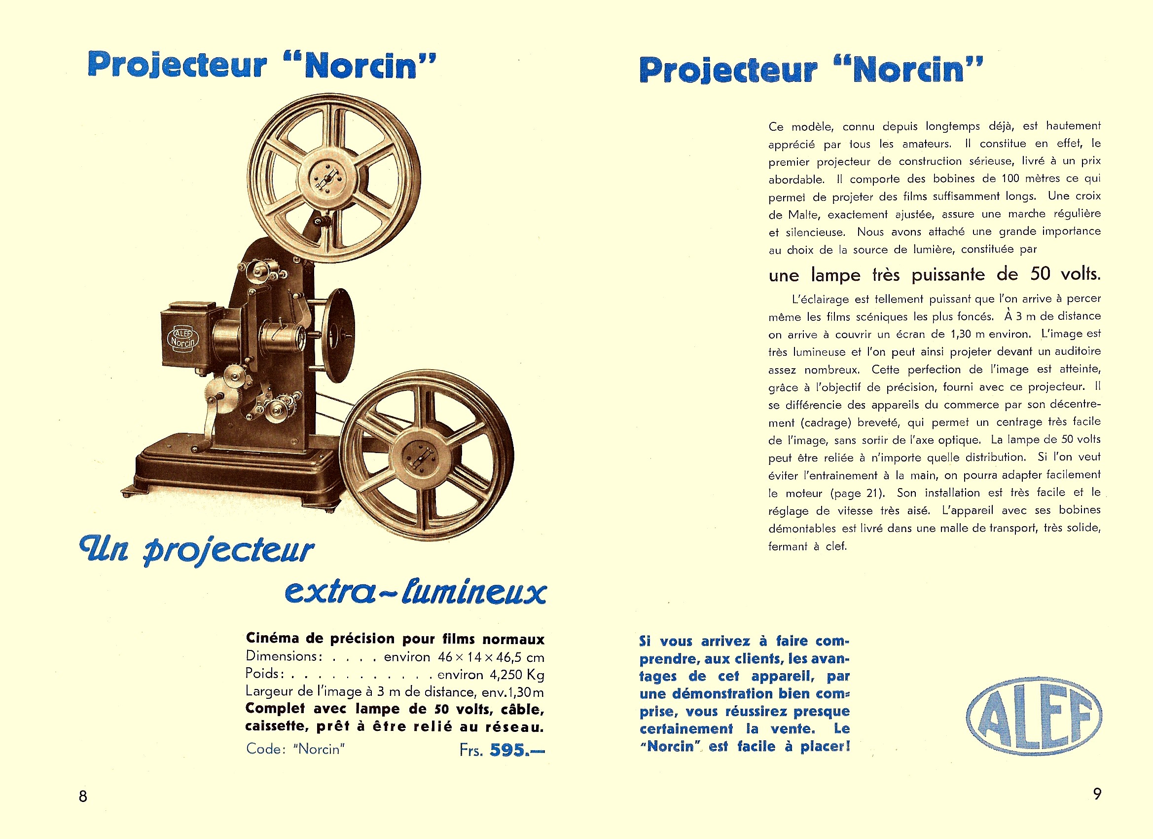


The only Alef I have ever seen in the flesh was in the possession of the late Peter Spooner. It has a lot in common with the above machines, especially the Bilcin, but I think may be later. The blue ones are a toy 9.5 Alef, courtesy Dave Humphrey.


--------------------------------------------------------------


These are ones I have acquired. The first one has nothing to say it is Alef, tho' the mech part looks a lot like the Dave Humphrey one above. As for the other, it has a strong resemblance to the Bilcin listed in the above catalogue
It is this second Alef on which I am focussing here - it is a strange admixture of quality and idiocy.


The quality I shall come back to, the idiocy is obvious - that ludicrously tiny lamphouse, the restriction in the size of reel it can take and the very small diameter lens - all the same faults as the Pathé Baby. And of course, also like the Baby, it has no feed or take-up sprockets, but this has to be viewed in the light of the fact that there is an intermittent sprocket and, although it is not in an oil bath, it is far from the loose, clattery affairs seen in 35mm toys. As I suggested in the context of the LaPierre, this may obviate some of the worst problems of sprocketlessness. (Note I do not seem to have the upper spool arm, so I shall have to make one.)
One other thing, however, makes the Alef stand out from the ruck. It seems to have a mechanism for handling notched films, a rarity outside Pathé projectors. I shall explain.


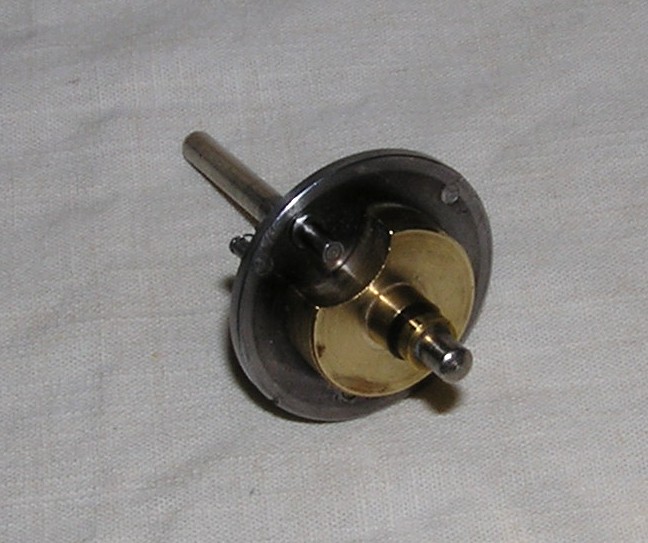

This first group of pix shows the heart of the notching mech. The main reasons I started on this projector were;-
a) the rust you can see on the base in the first two pix at the top of this piece. Luckily, it seems to be restricted to the side, and I have been able to re-paint up to the rim only - you can hardly see the join;-
b) I found a piece inside which I later identified as the pivot arm - see pic 1 just above - was flopping around loose and also the main gear was not turning over. I just could not see what was going on without a fairly thorough dismantling. What I figured out was that the pivot was not there, so I had to make a new one. Bit tricky since, as you see from the third pic, there is no room for any fixing on the other side as it would foul the Maltese cross mech. So it has to be a force fit cum friction hold - which is probably what went wrong in the first place. Hopefully it will work well enough, as the machine is unlikely to get a lot of use after all.
Anyway, the way this works (I think; not put it back together yet!) relies on the fact that the gear in pic 1 is not directly connected to the disc in which it is mounted - it is free to rotate - or, rather, the disc is free to rotate without taking the gear with it. The gear is only driven when the tongue drops into the docking station. This means that the pivot arm has two positions, which are controlled by the activating tongue. The tongue is tipped to the stop position for a notch, then is manually re-set for continued projection, ie with the gear locked in step with the disc. This is the default position, with the tongue held in the docking station (sorry - modern technological term) by the spring. The guide stud (which has a smaller diameter bit below what you see so the pivot arm slips underneath) acts to hold the pivot arm so it cannot lift away from the disc. In a further complication, the slit marked at the top (and I think there may be another near the guide stud) seems to engage with a spring mounted on a post that can be seen in one of the pix below. This acts as a sort of ratchet. All v. complex and I'm not entirely sure I've got my head fully round it yet. A slight worry is that I had to replace the spring - the one there when I started is too long to do the job my replacement is doing .......


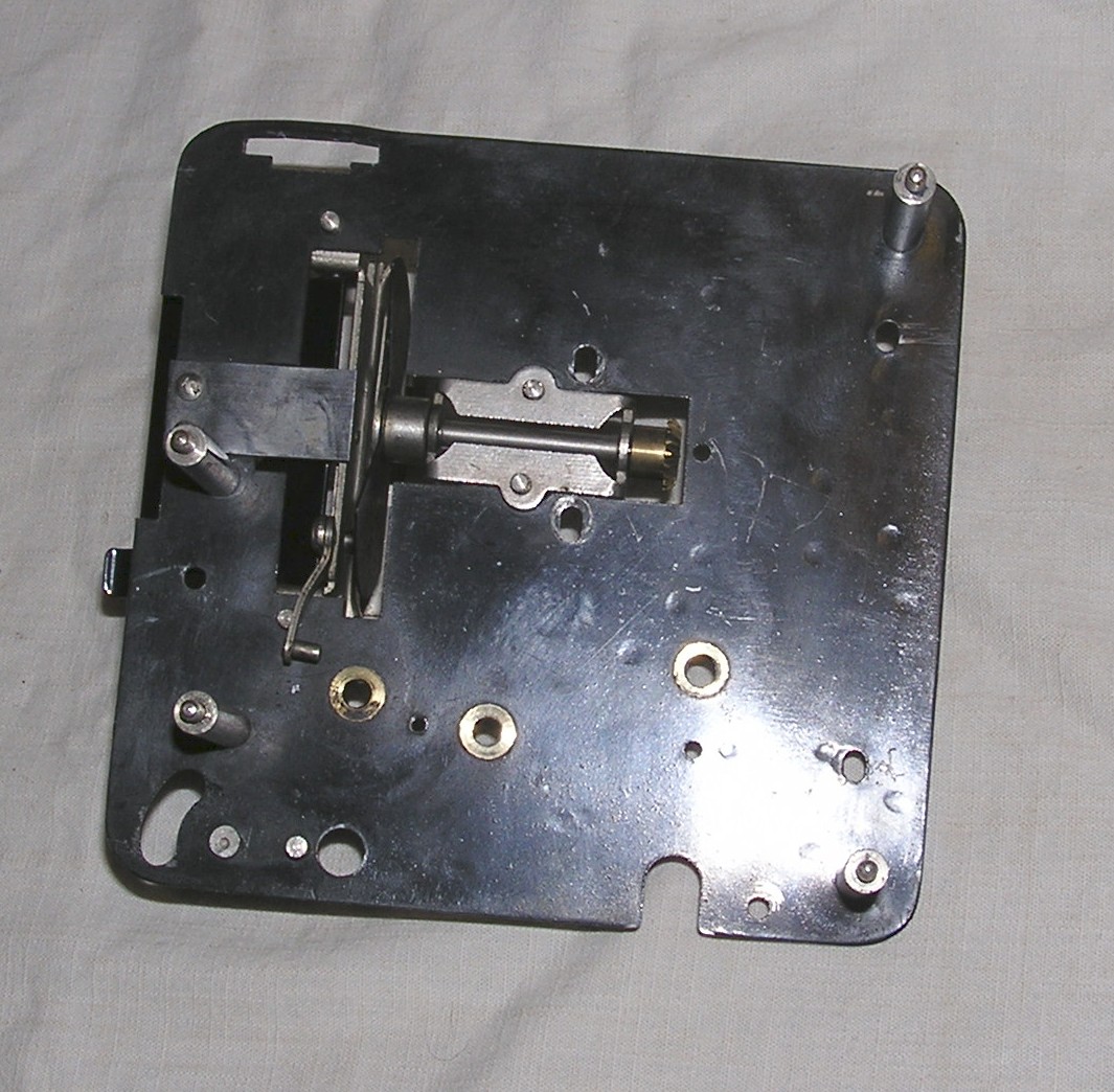
This set of pix is largely to show the quality of the construction - quite thick metal sheet, lots of bearings and chrome, bevel gears, glossy paint and whatnot. I must re-build to see if it does actually work!
Aaaaaargh! I got the Alef mech back together and confirmed my thoughts about how it worked. Then the activating tongue broke off! This not only undoes my work making the new pivot, but it is going to be an absolute devil to replicate the pivot arm. Les choses sont contre moi.
I did actually manage to make a new pivot arm, not as good as the original but it does seem to work tho' I have yet to try film. I  have also looked again at my Alef pix and it now seems to me that, certain minor differences aside, my machine is a Bilcin and the one with sprockets is a Bilcin 100. I am in the process of making a temporary upper arm; to make one to take cassettes seems a bit complicated right now - I've already spent a lot of time on this machine. It is however shiny and pretty. Must now get back to re-assembling the 200B Plus I've been working on!
I have now done pretty much all I am going to do for the time being with the Alef.


I have included a "before" pic at the beginning. The top spool arm will just about take a 400' reel, tho' obviously the bottom won't. I found a bit of ready-bent metal that just cried out to be adapted for this job, and the more dedicated may recall that a long time back I made a spool spindle with flip-over end thingy to prove to myself I could do it, and that has come in handy, too. I want to move on, so do not propose to make a cassette holder yet - I did try using one mounted on a spindle thru the core, but it just didn't allow enuff freedom of rotation and led to the film being torn. The cassette needs to be held by its body, leaving the core free to rotate jerkily as required. I can't really see any smoothing for the feed on the Bilcin but I think it's probably needed. But the notching system worked!
-------------------------------------------------------------
You may recall Illustra Enterprises. I remember Peter Spooner telling me of his frequent visits there; he described it as something of an Aladdin's cave, piled high with cine stuff. The proprietor was obviously a bit of a wheeler-dealer, as evidenced by the items in his lists. Later, he bought the 17.5mm Library from Pathescope when they lost interest in it after the successful launch of 9.5 sound. Peter wrote about Illustra in Flickers, many years ago. Here are some adverts of Illustra wares and a projector review.


The "Illustra" projector reviewed by ACW is not only obviously an Alef, it actually says so on the side.I saw one once (see photo) and my impressions of it were rather better than the Reviewer's. I suspect the 35mm machine is also an Alef.