Page 1
WHAT'S NEW Page 1
9th January 2014


A few more 200B bits for you. Pic 1 is the familiar plug used with many Baby projectors. Many of these have the rim or shroud bit broken off to a greater or lesser extent; with this one it was greater. This tends to leave the connectors exposed. I spent a quite inordinate amount of time with paxolin, superglue, Milliput and other similar stuff re-instating the shroud, then painting it Humbrol satin black. It will now plug on on the rear side of the machine, to which I have transferred the two pins from the front. The front socket will be blocked off. Part of the reason for doing this appears in pic 2. I found I had several 120v 150w valve-base, internal mirror lamps for which I have no conceivable use; this gives me a simple 110v connection to the machine. Worth experimenting, I thought. It was simple to add the new lamp socket, as the mounting lugs had fixing holes at almost the same diameter as the 200B lampholder. The new lamps are so much shorter I was able to connect wires to the existing contacts inside the original lampholder without making irreversible changes. Pic 3 shows the asbestos-free lamphouse back and side cover after de-greasing with Meths (2011 vintage, an excellent year) and a coat of dilute Humbrol black satin. Before painting, there were various small knocks and scrapes that had left bare patches, and the whole thing had gone that dreary, tired-looking dull grey. The thin paint does not affect the texture of the finish (apply thinly, mind) and certainly brightens up the look of it. I shall probably now have to do the rest as well.
31st December
Thank the stars that's the end of 2013, which has been pretty awful. Most of the last 3-4 months has been a tale of illness of one sort or another, culminating in cold which turned into a chest infection which has prostrated me pretty much since we last spoke. And then to have to endure Xmas on top of it. Bah Humbug!
If your memory goes back that far, you mite recall the Pax I bought off eBay and the sound smoothing unit which I did some work on. When I came to try it again in a rare lucid moment over Christmas, I found the warble was terrible. I can't remember myself exactly what tests I ran last June, so was a bit stymied. Tried reverting to the original spring arrangement for the twin post-drum rollers, but nbg. In the end I just removed them entirely and now seem to get great sound. It does, however, seem that what I may have done is to reproduce most of the effects of the old chute, with the extra-sprung rubber roller in effect providing drag in much the same way and therefore with much the same potential problems. Plus change........ Incidentally, neither this machine nor the Tony Saffrey conversion I have shown you pix of before ( "of which I have previously shown you pix") seem to use a roller onto the sound drum itself, which many machines do, eg Heurtier, RCA Hollywood. Is there a reason for this?
15th December
I mentioned below I was doing a refurb on a 200B. This is a machine I have had very little to do with, in large measure because a 200B once gave me one of the worst electric shocks I have ever had. However, I have mellowed in my old age and decided to give it another chance. Here is a progress report. I thought this particular machine was worth the effort as it is a 200B Plus, complete with framing device and functional still picture arrangement.
Although the machine is dirty, the brightwork has a good thickness of chrome and is cleaning up nicely. I have tried to do a before and after for you with the bits from both sprockets. Not too successful but enuff to ensure a fat lip for anyone who asks which is which.

It does show clearly just how much there is to do with so many bits and pieces to clean, many of them of awkward shape and mostly coated with the accumulation of 50+ years of dirt as, of course, nobody ever cleans a projector. This one also had Bakelite problems - the base was in two pieces and the lamphouse top was a bit cracked and chipped. Rather to my surprise, I was able to get a good strong repair to the base; normally, any glue I try proves weak. This one is a superglue - I think they are all different and this one, by luck, happens to be suited to Bakelite. I filled in a hole where a chip was missing on the LH top with Milliput, then smoothed and painted. Looks quite respectable. If you know the 200B, you will no doubt have come across the problem of getting the (designedly) rough patches of the Bakelite to look anything other than scruffy. I have cheated and applied some much-diluted satin-finish black enamel. It has to be thin and thinly applied or it just looks hand-painted and ugly.


I decided to clear the stuff that I assume is asbestos from the lamphouse. Given how widely it was used, I think we make a bit too much fuss about it but I don't spose everyone would agree. I soaked it in diluted varnish to bind it together so it didn't make dust as it came out. I am still considering the lamp issue. I think it's going to have to be 110v somehow, as I want to set this one up with just a single 110v input at the back, using the kind of plug found on some Babies; a squat, 3 connection job with two sockets and one pin. As a separate but related exercise I am seeing if I can re-habilitate a much-broken one of these using superglue, paxolin and filler. I have transferred the two front pins used for the main input to the back, leaving one socket which will take an earth. I really don't like not having an earth, even at 110v. Incidentally, some people seem to find 110v worrying, and are reluctant to use it. It is in fact one of the simpler jobs to set up a 110v tranny that you can use for any machine that needs it, in preference to the evil resistances (death traps, if you ask me).
As for switching, I have more or less decided to add one to the sloping front just above the Bakelite base. Rather than make holes (which would be wrong) I have made up a replacement strip to fit the gap. I shall probably use a centre-off switch to give separate motor and lamp capacity, as with the H. And while I was at it, I thought I would do you some pix of a naked 200B as I know you like that sort of thing.
6th December
Have completed the H and its story is on H Page 2, at the end.
3rd December
Had an enquiry about the circuit diagram for the Ampro Premier 20, which prompted me to dig it out. It was on Gestetner-type paper, and not quite accurately joined together out of two separate pieces. It therefore required quite a bit of photo-shopping to make legible. Did the wiring diagram as well. Also found a pic I had forgotten of a Premier-style machine in silent form but convertible to sound.


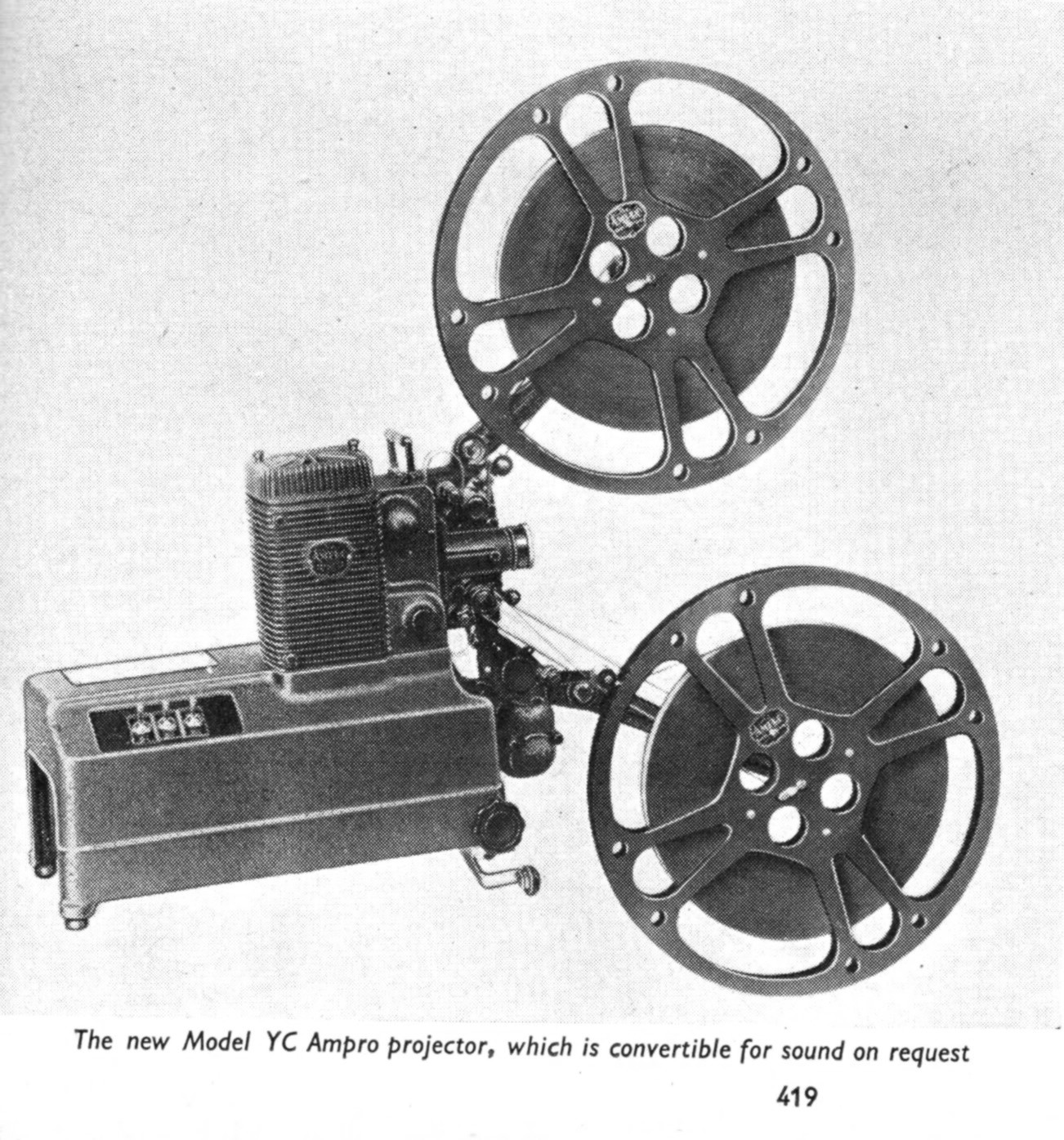
30th November
Currently engaged in major refurb work on both an H and a 200B. More on the H at the foot of the H page. All I can tell you about the 200B so far is that there is an awful lot of cleaning to do, but it is rewarding to find that most of the brightwork is chrome of a decent thickness and unless badly attacked can come up v. shiny.
21st November
I have had an enquiry from overseas about parts for a Bolex G3, specifically for the plate carrying the two condensers, the inner lamphouse sleeve, the lamp-holder and the resistance (and its knob) that controls the current to the lamp. Does anyone have, or know someone who has, a junk machine that includes these parts that they could pass on? The usually sought-after parts, eg gates, sprockets etc - are not needed.
I'm a bit concerned about the Bolex G3. I have been looking at mine in response to an enquiry and, incidental to that enquiry, I recalled a concern I had first felt a good while ago. It is simply this; I do not think there is enough "travel" on the sprung, back part of the gate to allow the claw to skate over the film until it finds a sprocket hole. One of the main points of "inching" a projector is to enable this skating to happen, so the claw is properly engaged with the perfs before starting the motor. But with the G3, this doesn't seem to happen; the claw can dig in and tear the film, because the sprung gate won't move back far enough out of the way. When the rear gate assembly is hinged back for threading, the gate seems to have just about enough travel, but when the assembly is closed for projection, much of that travel disappears. Now, the springing on the gate assembly as it hinges back might be able to provide some additional slack, but it doesn't, because the spring is much too fierce.


These pix should help show what I mean. The sketch shows very roughly the shape of the gate spring. It has an over-size aperture hole (as it's a bit behind the plane of the film). Each end has a shaped portion, a bit like I have tried to show in the edge view bit, to give a "shoe" which is actually in contact with the rear of the gate. It's fairly thin metal, and gives what seems to me a sensible degree of springing for a gate. The threading spring, however, is a simple curved strip of much thicker metal and gives a much stronger spring effect.
One of my problems is that I'm not at all sure that any of the Bolex G3 mechs I have are actually good standard examples. One is a sound machine, one is a constant-speed silent, one has been hacked about. So I can't be sure this is a general problem. Anyway, can anyone shed any light on this matter? Were there complaints at the time about the way the G3 treated film? Has anyone else met the same problem? Could it be that the threading spring needs to be made slacker to allow more travel?
Any thoughts or guidance would be most welcome.
---------------------------------------------------------
Have I showed you this EKA? I don't normally do 35mm toys but it was red and shiny and had a film ....... Then I thought I mite as well show you these other bits as well.

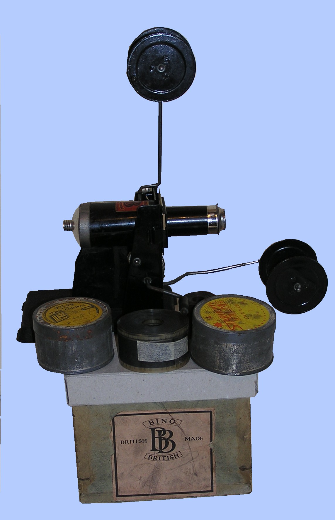

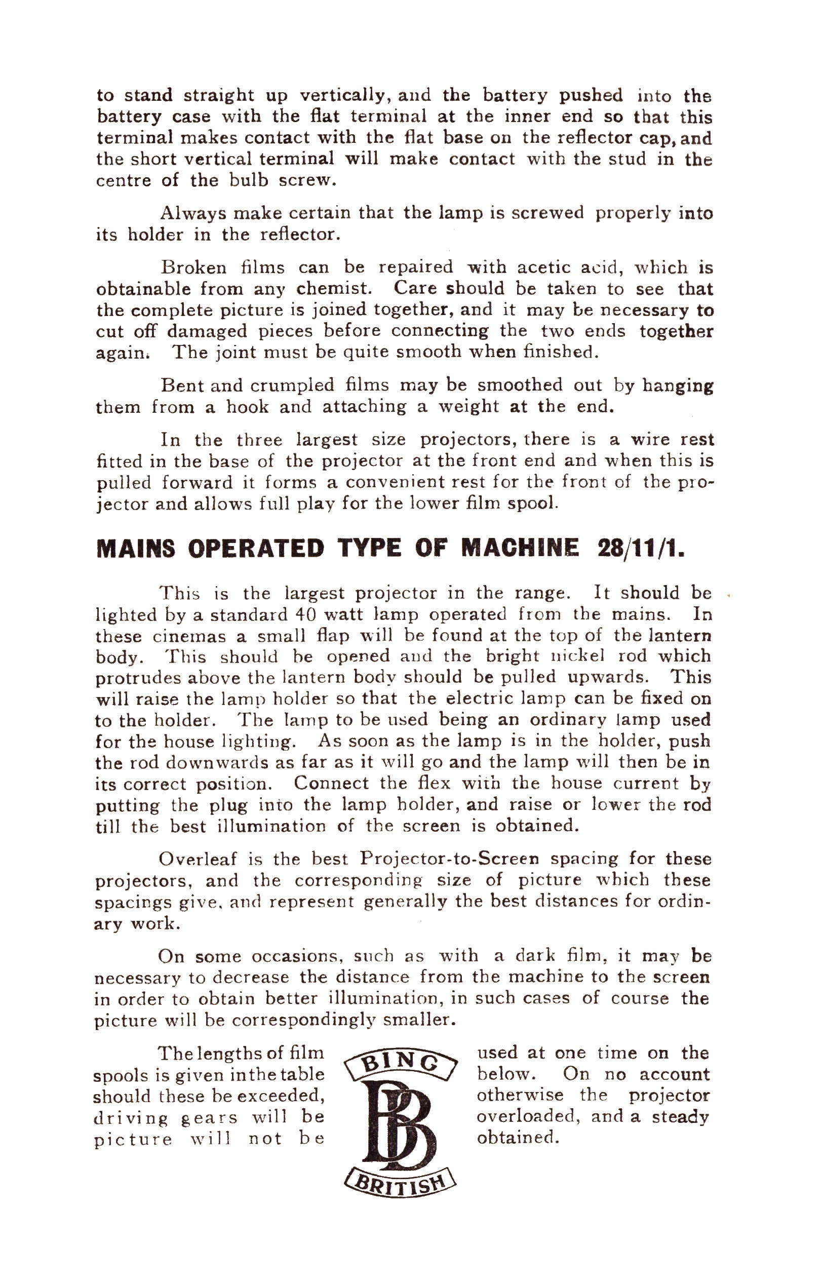
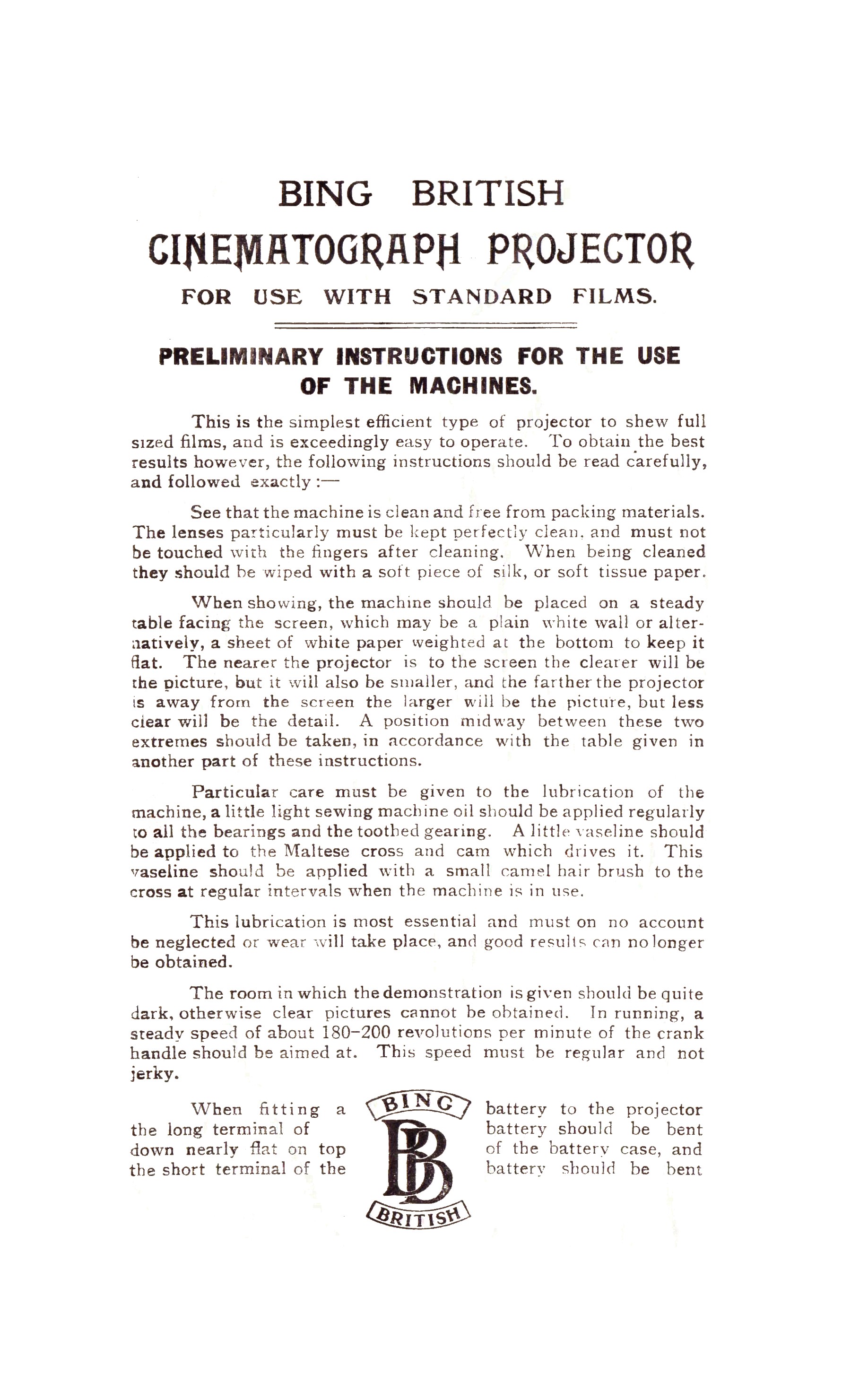
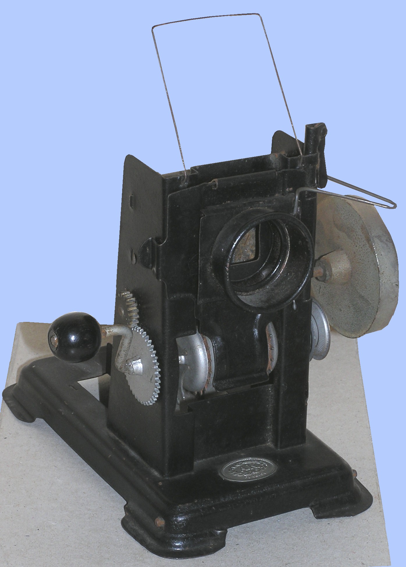

They are a Bing British and its Instructions (must try to make a better copy), acquired quite incidentally with other stuff, a part 35mm toy (A.F. it says) and finally a replacement shutter for a Gaumont Chrono, made for Chris Bird from a template provided by Mikael Barnard from one held by the PPT.
20th November
Nizo solved the problem of multiple gauges in an interesting way - on top of a base, with a permanent lamphouse, sits a separate, interchangeable unit for each gauge.


Pix 2&3 show my Nizo, with a 9.5 mech fitted and a 16mm mech beside it. 4&5 are the front page of the instructions.
Below are some diagrams from the instructions with the key to the parts. I won't trouble you here with the rest of the instructions since, as you can see, they are in French, but I will include them elsewhere for the record.


The instructions refer to 8, 9.5 and 16mm mechs, but there are strong rumours of one for 17.5, too!
19th November
A beyootiful Powers 35mm machine spotted by Chris Bird


15th November
I've been doing a fair bit of fiddling with the site, especially this page; please let me know if you spot any problems.
Some time ago, maybe last year, I commented on what I suggested mite have been slight misrepresentation on the part of Siemens in describing their Beta mech as non-claw. I have just today found, while idly browsing my files, the following.


3rd November
Does anyone have any info/pix etc please on the PAS recorder which, I believe, used 16mm film to record evidence of "kill" or whatever by fighter planes, WWII era. These are, I think, the films for which Specto Analyser projectors were produced. More on Analysers wd be helpful - I have very little in written form. This is in response to a query from a Museum oop north.
I am a Genius!
As you know, many years ago when I was young and unskilled, I made a 28mm rewinder from an old pair of 35mm arms. It has never been quite satisfactory and not least had no 1:1 speed for film checking and cleaning. So I finally made some adapters to fit my Muray rewinds. Yer tiz.
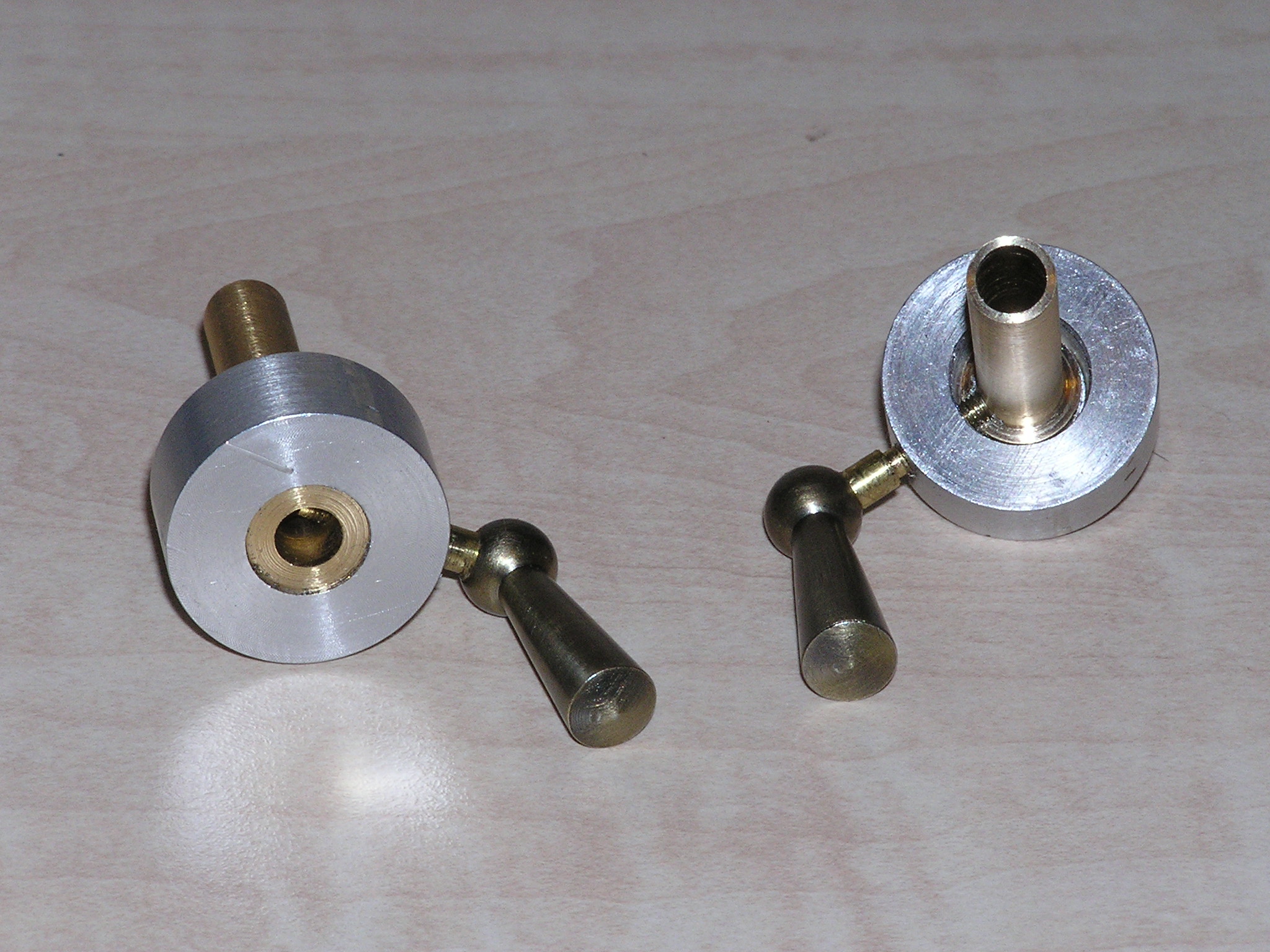
They fit from the back of the spool, with the long tube doing the job of making the rewind the same diameter as the inside of the reel. 28mm reels have a protrusion on each side of the centre, with two notches that engage with the rewind or projector spool arms, sort of a dog clutch. The outer protrusion goes into the hollow in the alu ring, where the brass tube goes thru. The screw with the neat handle (something inherited that I came across the other day and thought AHA!) engages with the notch, too. (At the opposite end, the notch engages with the locating pin on the rewinder shaft). Finally, the screw clamps down onto the flip-over retainers at the end of the rewind shaft , which are left unfolded.
Bet you're impressed!
1st November
A long time ago, in a galaxy far, far away ............
One of the (many) problems with 17.5 is the state the spools get into. Rust seems to have more than one form when it comes to 17.5 spools, all of them damaging and ugly. Flaking paint and rust, roughened surfaces and edges and likely interaction with the poor old film, which already has enough to contend with. Quite often, added problems result from historical attempts at over-painting. The problem of dealing with the spools is that they are very thin metal, so rust penetration can even make holes but, more important, any kind of aggressive treatment like shot-blasting is out. As the surfaces are in complex shapes for stiffness, including a rolled rim, hand sanding is difficult and machine sanding virtually impossible. And whatever you do, rust creates pitting of the surface to a depth that simply cannot be sanded out. So results from any clean-up and re-paint are only ever likely to be moderate wherever significant rust has occurred.
Anyway, it was quite a long time ago that, in a fit of enthusiasm, I dismantled a number of those spools that were rustiest with a view to re-painting. I swiftly discovered that it was very hard work and that there were the various issues I have outlined. So things stalled and fell off the radar for a long time. Eventually, decided that some result was better than nothing so gave a quick sanding of critical areas (especially inside parts that could rub on film) and tried to find a cheap way of getting them done. I ended up with a chemical treatment to kill rust and clean up, prior to a coating of shiny (that was what they were using and beggars can't be choosers) black polyurethane paint. Even then it wasn't what you would call cheap - a couple of quid PER SIDE, ie 4 - 5 per spool. I did a batch of 28mm at the same time. Wherever there is pitting, it shows up and the finish is far from perfect, but the rust has gone and I don't think it will dare to come back and I have a batch of reasonably respectable spools.

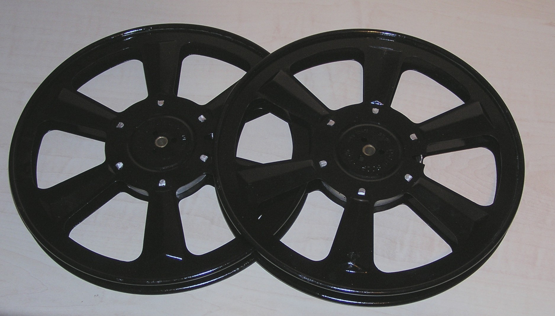


There matters lay for some time as I was a bit discouraged at having to settle for second best and had also realised that I now had to re-assemble the spools and re-mount the films from the cores they had been occupying in the meantime. This looked like a lot of work and I was worried too about the risk of breaking the lugs that fold over to hold the circular core to the sides. Said cores are made of aluminium and what limited experience I'd had in the past suggested breakages were likely, with the risk of making the reels go all floopy and unwilling to do their duty.
As you can tell, I had definitely lost enthusiasm and demonised the whole process. Anyway, I finally decided to bite the bullet and at the least get the spools back together. It helped that I discovered relatively recently that, while aluminium hardens with age and so is rather more brittle, this can be reversed by heating. Experimentation showed that the softening effect was quite marked, so I began to entertain hopes that at least some of the lugs would survive. So the process goes like this:
Heat each lug of circular core with blowtorch for about 4 seconds. Any longer and they start to melt. There are 10 - 12 lugs per spool.
When cooled, straighten all lugs with pliers, as they aren't quite flat when you take them out of the reels.
File lugs a bit as they are "creased" and uneven.
File lightly centre hole of each spool side - the cores were originally a slight "force fit".
Fit circular core to one side of spool. It's fiddly. Then fold over lugs, going slow to avoid breakage. I always use a lump of wood as it's softer and less likely to scratch when (not if) you slip.
Add brass centre sleeve. If you fail to do this, you will be sorry. Unpicking a reel you have just done to fit the missing sleeve is not good.
Fit second side and bend lugs, ensuring inner brass sleeve locates correctly.
I reckon I was doing it about right when I did not break a single lug on something like 30 spools. But what a job - and I still have to re-spool the films, if I can find which ones are on cores. I did have to replace 4 or 5 lugs that hadn't made it thru the original dismantling process (didn't know about the heat thing then). See pic. I actually cut a notch into the side of the alu to give the bend in the new lug somewhere to go. I managed with some superglue, just. Nothing I've tried before works eg araldite, epoxy putty.
-----------------------------------------------------------------------------------------
Here's a sad case. This early Agfa 16mm is interesting, but it has fallen victim to the usual appalling storage conditions and to the dreaded Mazac distortion.

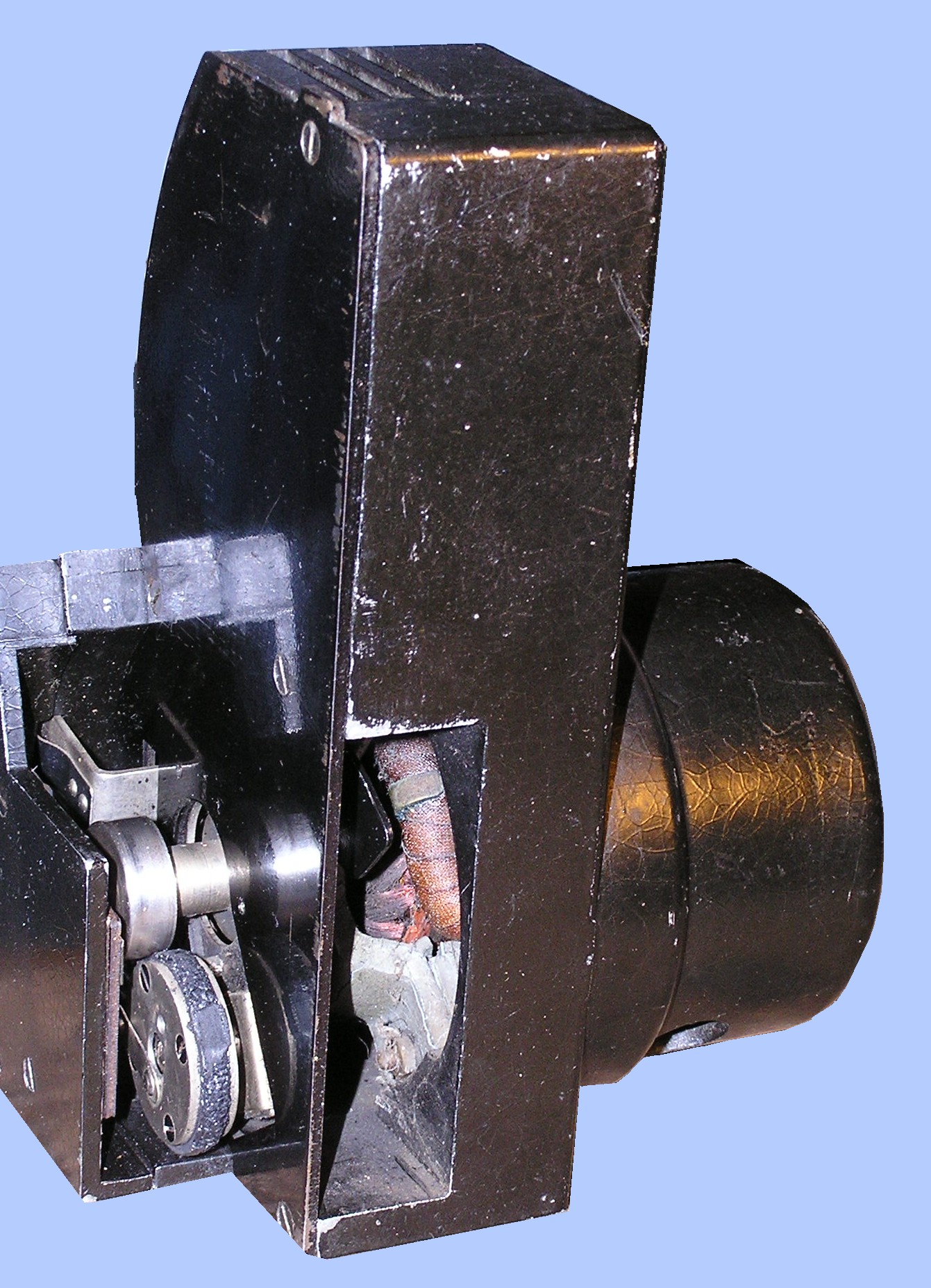
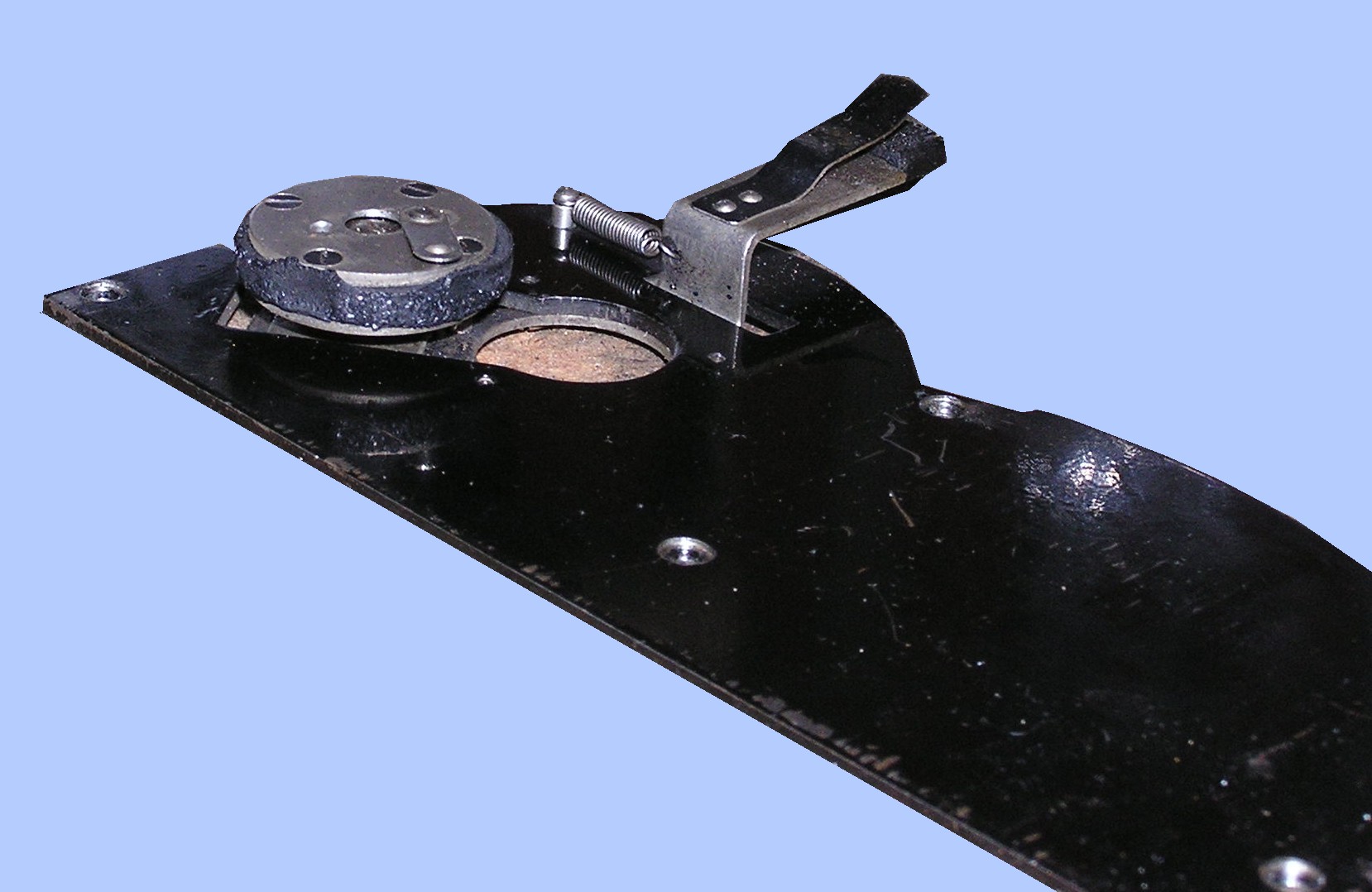
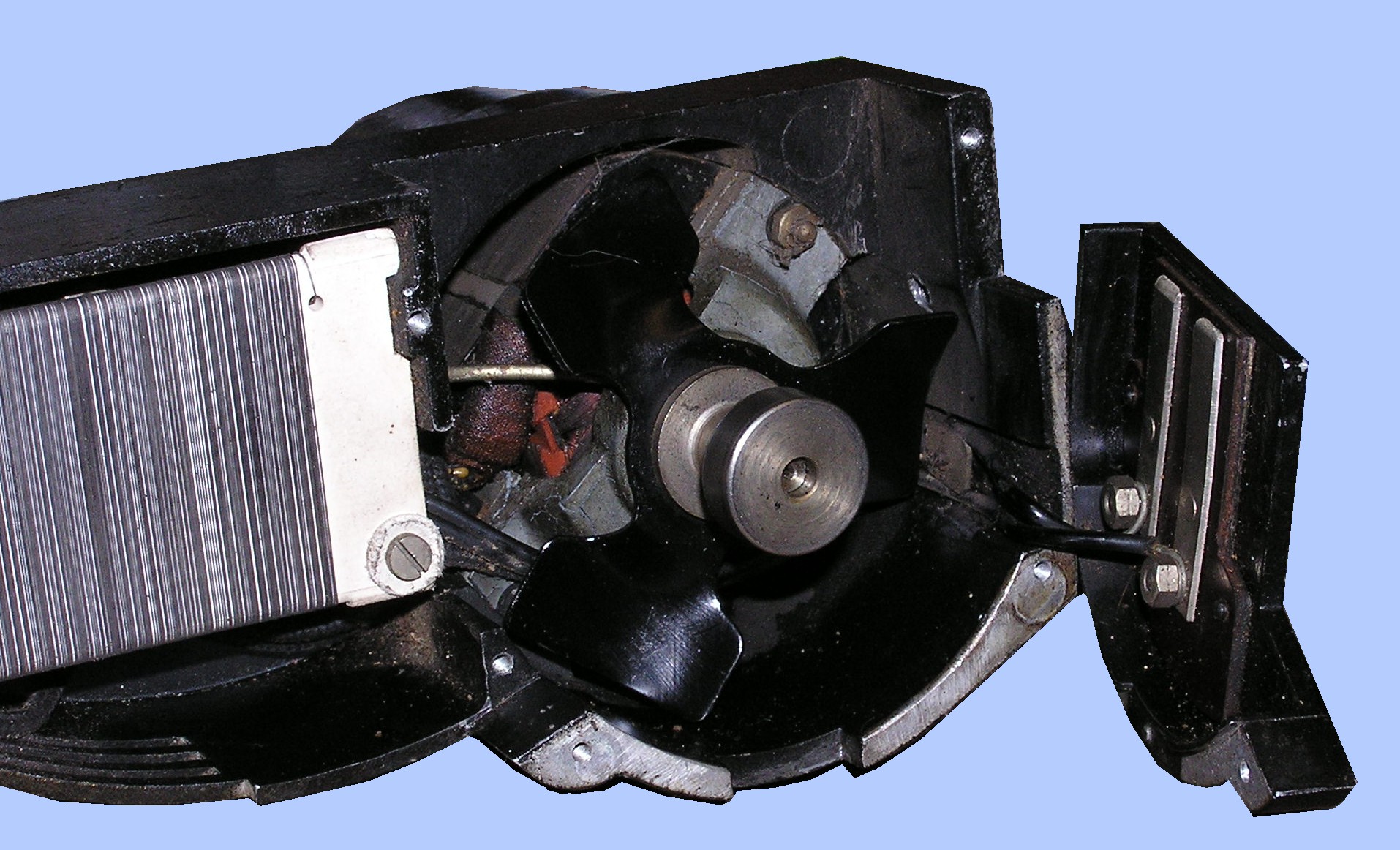
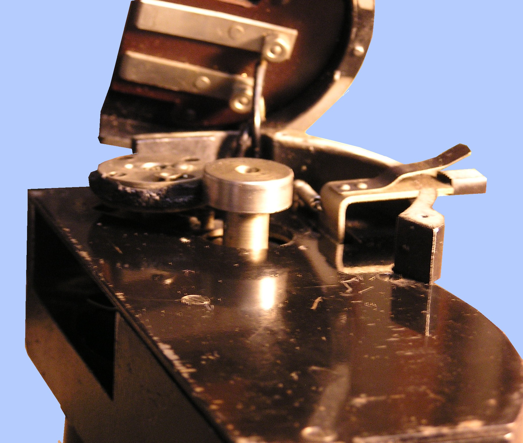
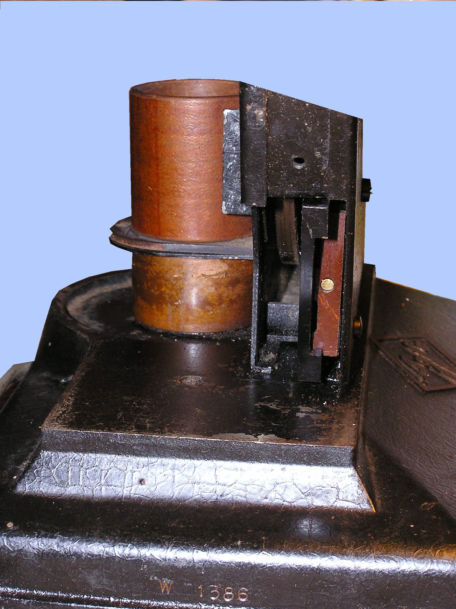
The motor, with speed control and a 110v/220v selector, is a separate unit that plugs into the back of the main mech. In pic 3 the paxolin strip on the right is sprung and gets pushed back, exposing contacts the motor unit connects with - bit like the arrangement in a standard 13 amp plug I spose. The motor has a smooth roller on the end of the shaft, which engages against a rubber-coated roller (pic 4). This also is in contact with a larger drive wheel inside the mech; basically the rubber-coated one is like an idler but actually does a job of work in transmitting the drive.
24th October
New! Improved!
A certain Mikael having arf-inched my 17.5 rewind adapters, I have been forced to realise a long-cherished ambition and make new, better ones. Here are some pix.
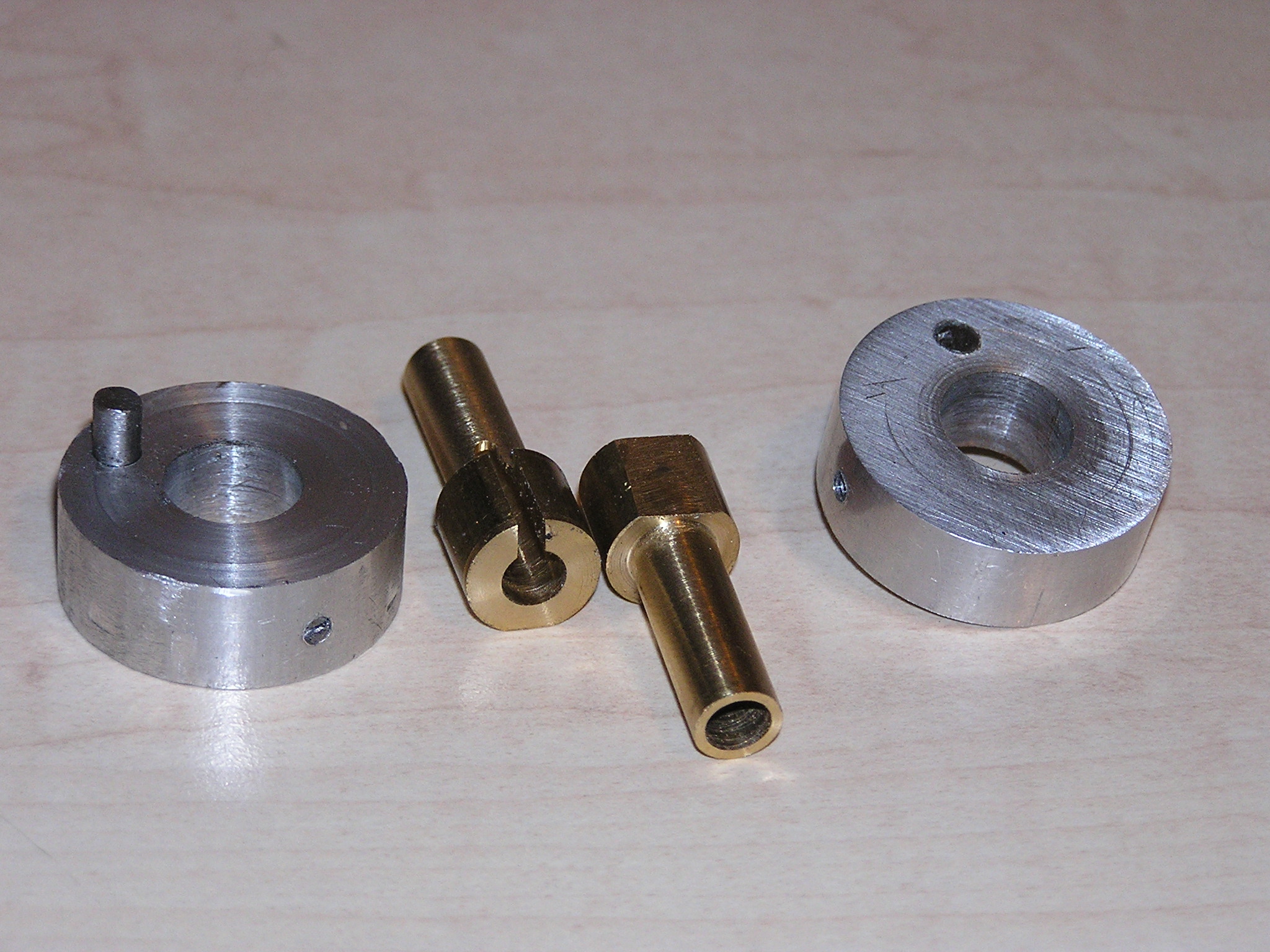
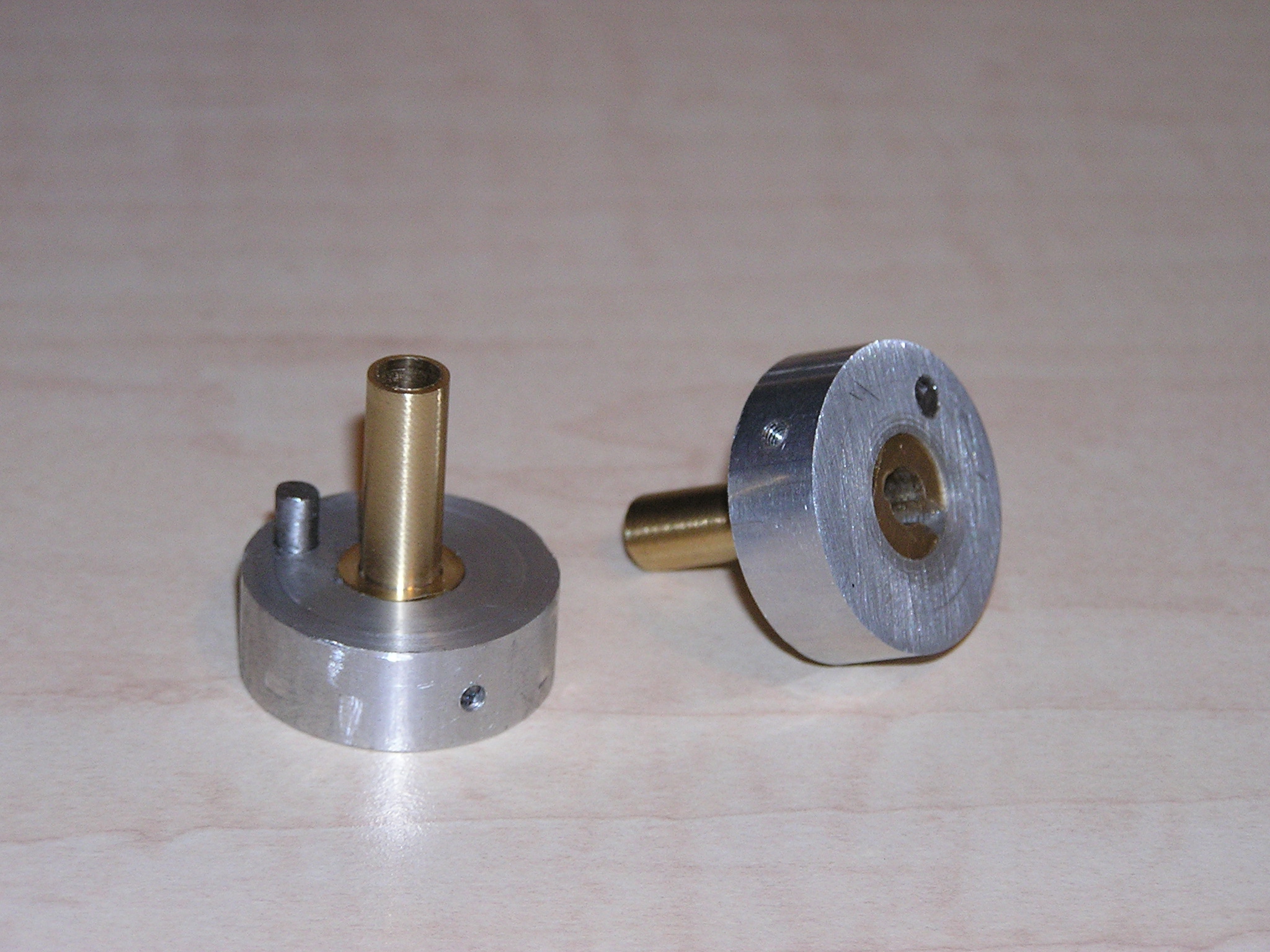
As you can see, it's a game of two arfs, Brian. That's just the way it turned out - I originally thought I would just force-fit a tube into the larger bit, but then I thought it mite not be strong enough to stand the pressure, so by various serendipitous steps, influenced by tools and equipment actually to hand, this is how it ended up. The brass bit is held in the alu bit by a grub-screw onto a flat on the brass. These are designed specifically for the Muray type of rewind arms. The original ones had just the alu bit, with a smaller (6mm) hole, obviously, and sleeves to make the spindle of the rewinder up from 6mm to the 8mm of the 17.5 spool. The problem was, the sleeves kept sneaking off inside the spools - either in the bore or, worse, with some of the smaller alu ones with no separate core, inside the body of the spool, whence it was tricky to extract them.
4th October
Had a bit of a fallow period; most of what I've done has been trying to sort stuff I want to shift in time for the Film Fair season. Why do we have to have three within weeks of each other? (I won't mention the abduction by aliens for vile experiments as you probably wouldn't believe it.) Then there've bin hols AND the annual pilgrimage to the big Fair at Argenteuil. Here is something I found there, which casts an interesting sidelight on Bolex.
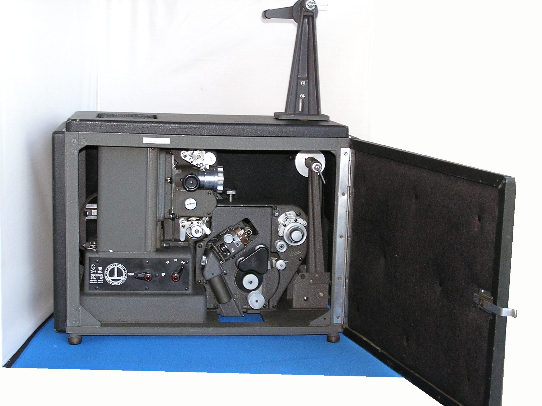
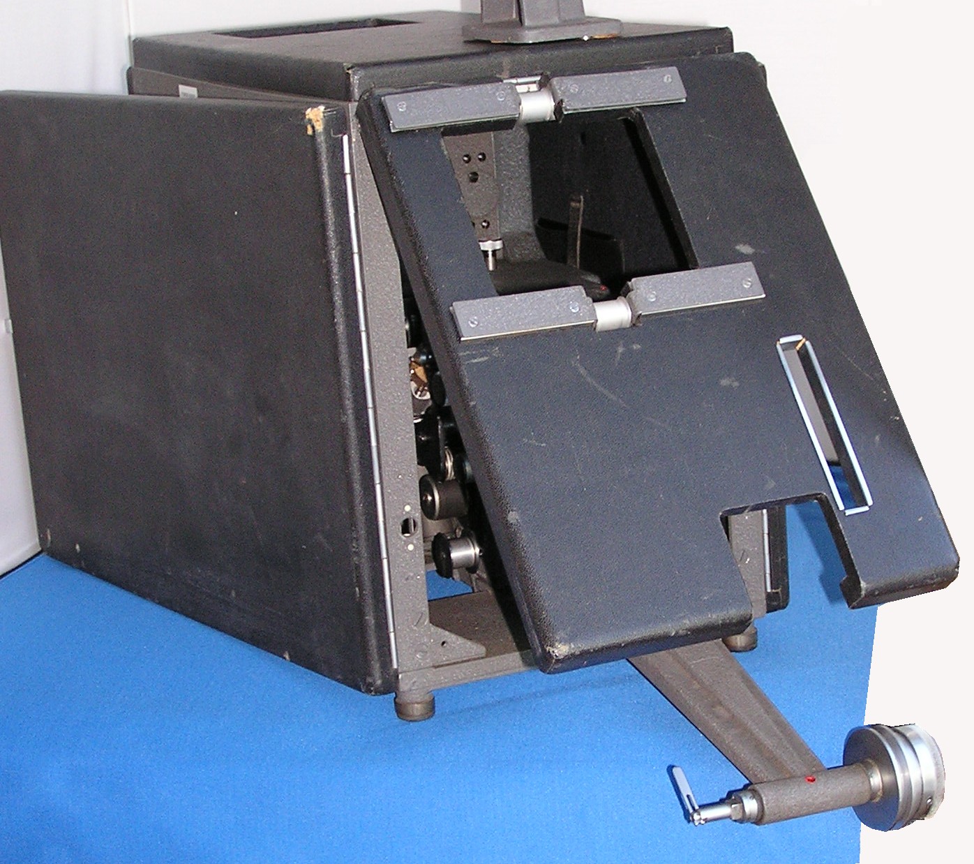
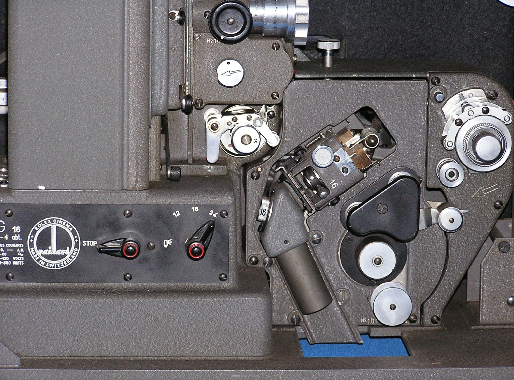
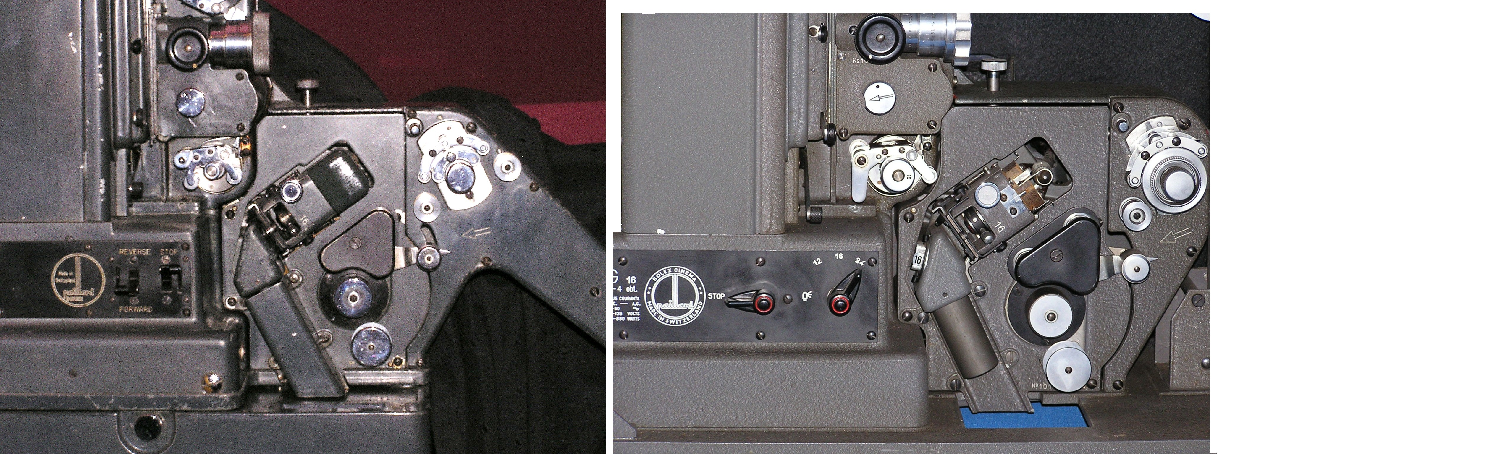
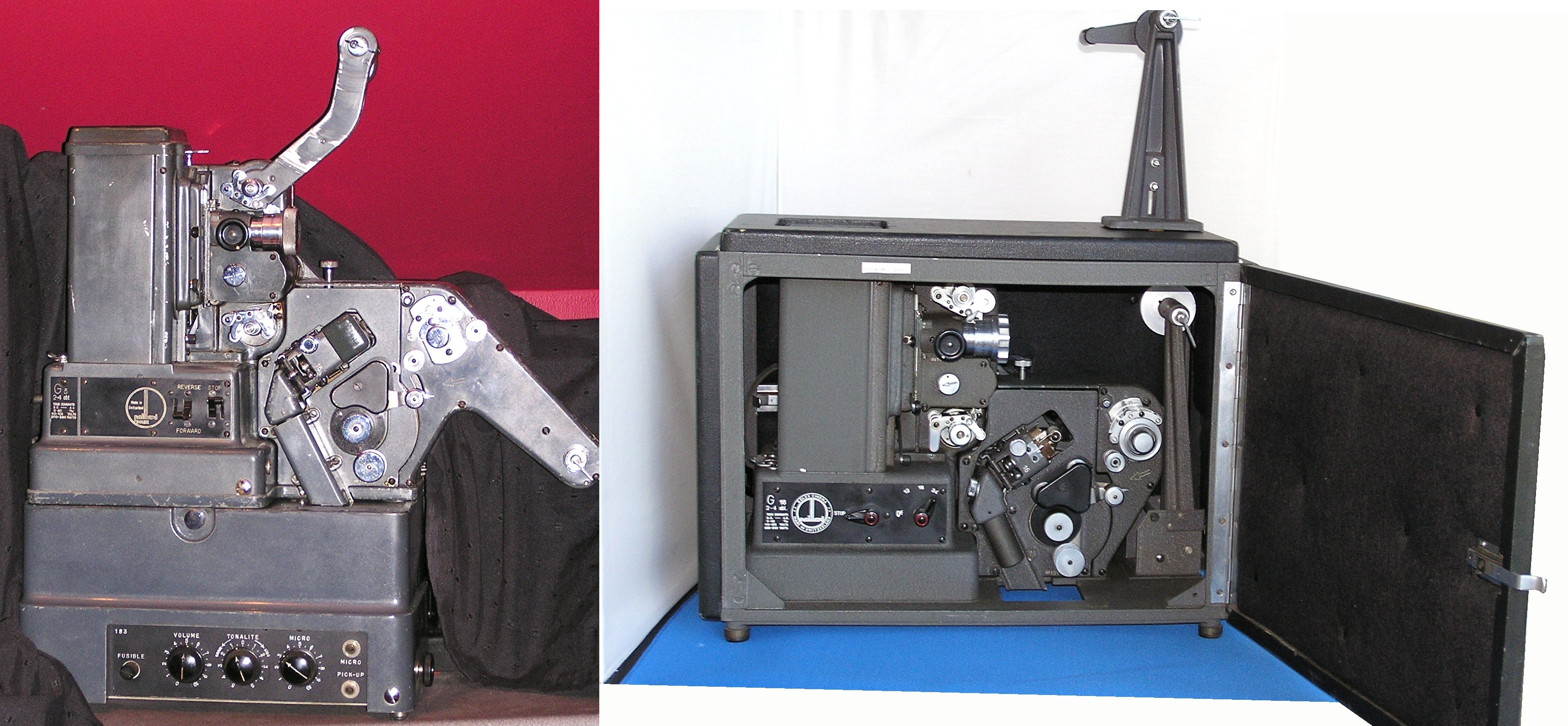
Last two pix comparison with the Bolex G3 sound I've had for years. One of its main problems is it's very, very noisy in operation. Then we have from Argenteuil a 16mm-only (did we ever have a G16 in the UK or were they all multi-gauge?) version in a blimp, both projector and blimp obviously being specially made for each other. The front end of the sound unit is modified as it has no integral spool arm (ditto for top spool arm) and the motor and lamp switches are combined in a two-position switch on the front rather than a separate lamp switch at the back of the machine. Interestingly, there seem to be fixed speeds of 12, 16 and 24 fps. The blimp is obviously tailor made; as you see, the front swings up to allow the front arm to drop down (the other end also swings open). Note the giant hole needed to allow the image thru, given the lens is so far back. There is however some evidence that there is provision for extra pieces to slide into place in slots top and bottom of the hole. You can just about see this if you blow up the last pic. This could actually be very useful in providing side masking. Missing are the amp, obviously, tho' this matters little as one would put a diode of some sort in the path of the sound near the top, close to where the light from the exciter passes thru the film, and the cover for the exciter lamp, tho' this is just a bit of thin, shaped metal so should be possible to duplicate.
My recollection is that a lot of the noise of the G3 came from a mechanical governor in the mech. The provision of a range of fixed speeds suggests this one is more like the odd silent version I have, which has some sort of electrical speed control that provides the same. This I recall as being quieter, so this blimp might be more effective than I thought at first as it has less noise to contend with. Plenty of areas to explore, then. Yet another project.
11th August
I may seem to have been idle, but a fair bit has been happening, quite apart from a weekend away and a granddaughter weekend visit. I have been sorting and  checking various films with a view to sale, but it don't seem to diminish the pile much. Nothing terribly exciting so far, I'm afraid. I've also been working on a couple of what I call Silent Paxes. I acquired these some years ago from France and never really did anything with them. As I have been focussed on the Joinville range of late, I decided to have a go. The one shown here is complete and working (tho' it's not yet had a film thru). It basically only needed a good clean and oiling. But as you can see, apart from the amp, sound drum and sound reading bits, it's identical to the Pax as we knew it here in the UK. This includes a sound mask in the back gate and identical speed control for 16 and 24 fps. The other one was a different kettle of fish - casing (even more) battered, arms missing and a mazac'd pulley. I did in fact have a steel pulley at a fairly advanced stage of completion that I roughed out years ago, so I finished it. Works OK, but I can't be sure I've got the shutter phasing right until I can test it. At the moment, the motor is playing silly devils and I need at some point to go back to it. This was bought basically as a spares machine, but it mite be fun to experiment with re-motoring and adding sound.
25th July
I have decided to round up various pix I can't recall using here before, with no explanatory text (except that the last two pix look like an evil Russian Son (ugh!), and put them in a Side Gallery.
23rd July
Most of my time recently has been taken up with trying to deal with the 'orrible 'eat. I do not function well at temperatures such as we have had, and have really just been sitting around, waiting for it to go away, and unable to get much done.
One project I have been plugging away at is trying to trace the wiring of the PathPM of which I have told you. It is about as insanely complicated as I thought. Here are the main parts of wot I have found - no guarantees, mind , E&OE etc. I will try to do a final pic of the other, more peripheral bits.


I have also, with huge labour and difficulty, produced as good a version as I can make of a virtually illegible and certainly un-photocopyable "blueprint" (it's mainly pinkish, actually) of the amplifier circuit diagram. I'm sure I haven't got it all right, as it really is hard to decipher, so if there is anyone out there who can correct me, I would be glad to hear.
The switch wiring diagrams are actually based on the silent version of the PM, labelled simply the P, which I acquired on ebay. It seems to have the socket for the neon strobe light, the amp connection in the base of the lamphouse and a gear on the back of the second sprocket which would mesh with one on the extra sprocket on the sound version. And for all I can see, the wiring is identical. I spose I could transplant the motor to the sound machine, but at present I am not so minded. I don't actually think much of this motor. I don't like the variable pulley, or the dodgy positioning of the start cap microswitch (and I am clearly not the only one to experience the problem) which renders it likely to be knocked into a permanent "on" position. All I am really interested in is optical sound (it's not as tho' there are masses of mag film out there). Also I hate push-button controls - too plastic. It looks to me as tho' the entire motor, switch panel and caps could be removed as a unit and preserved for a possible future purist willing to pay to have the motor re-wound. It should then be possible to use one of those B&H DC motors and run it from the lamp supply (with rectification, of coarse). Has anyone actually done this? A machine with a single external 24v supply would be so much easier.... And I could fit some nice, positive, metal toggle switches. Anyway, back burner for now for mature reflection.
19th July
Martin Jones tells me that the RCA 1600 continued to be produced as the Viewlex 1600 after RCA stopped making projectors, and that several machines were in fact produced under both labels.
17th July
http://m.flickr.com/#/photos/32223541@N05/6031754472/in/photostream/
Chris Bird has sent me this link. I am filled with jealousy.
14th July
Over the years, I have built up a surplus of Debrie D16 mechanisms - not amplifiers, just mechs. As you know, the Debrie mech with its curved base is no use without the matching amp. I haven't been able to get rid of more than a couple, so I've taken some completely to pieces, mainly to steal all those lovely nuts and bolts and a few other bits for which I can see a possible future use. The rest, I'm afraid, will end up in the tip as I simply do not have the space. So if you want any Debrie bits, up to and including a complete mechanism, now would be a good time to speak. I shall put and ad in the next Flickers, then that's it. I hate to do it, but I can't see any alternative4. I can see the same happening to many older B&H machines, too.
I have added a bit more about the PathPM (Pax) in the Joinville section. I sent the motor away for repair, but it apparently can't be done in a way that would allow it to fit back into the machine wiring system without a wiring diagram, and can't be done at all for the two voltages - it would have to be 240v only. So I have asked various people who might know of one, but my hopes are not high. I don't recall Pathever going in for repair manuals etc, and I suspect few if any existed outside Paththemselves. As a precaution, I purchased on ebay a 2-sprocket silent version (thanks to Terry Vacani for the tip) which seems almost identical, to the extent of having a few bits relevant to the sound machine but not the silent. I am now attempting to draw up a wiring diagram myself, based mainly on the silent machine, which has had little if any alteration, unlike my sound one. It's the sort of thing that does my head in. I spose I could just transplant the motor, but I am a tad reluctant without exploring the possibility of keeping both running.
2nd July


I thought I would share with you one of the worst examples of outright projector vandalism I have ever seen. These pix show the claw assembly of a Heurtier Superson, ie the tri-gauge mag-sound-only one, like the one shown. Not only were all 3 pins of the claw bent severely, the frame too was badly bent - you can see it bowed upwards in pic 2. Worst of all, the cam - made of paxolin - has been damaged, tho' how seriously will not be evident without further tests. Such arrogant stupidity, compounded by brute force and ignorance, is inexcusable.
While I have been trying to rescue this machine, I have finally gotten around to re-assembling the silent Heurtier Supertri which I reported on way back. It had suddenly seized up, so I had to pretty much dismantle it, but finally I have got it working.
29th June
Have been having a vigorous debate with Mikael Barnard about the GBL516. He recently came by one, but was deeply disappointed with the sound - low and muddy - and the problem of lacing the film thru the curved gate. The latter is not something I have experienced before, but I have now - there must be a knack! However, the sound I felt we could do something about, as both my machines had much superior sound. With my new, partial, second-hand wisdom, courtesy of electronically-minded friends, I decided we should change the capacitors - the low-value ones of 0.1, 0.01, 0.02 μF and simlar. These tend to have working voltages in the range 300 - 500v DC, tho' one or two of these were even higher. It was the usual b***** of a job, because of the usual problems of difficult access, replacements far smaller than the originals and bits of wire breaking off when you are not looking. But it worked, and together with a good clean of the sound optics, delivered far brighter sound with much greater volume.
Naturally, the lamp went while we were fiddling about, so I had to dig one out from the attic. It came wrapped in corrugated card as usual, but enclosed a note from a cinema manager, (the vendor). This stressed the importance of special care when installing lamps that were unused but from old stock, recommending 10 minutes at 12 - 50v before fitting and applying full voltage, in order to (greatly) extend the life. Low voltage warm-up circuitry that avoids the sudden shock of full voltage is a familiar concept, but I had not heard this variant before. Seeing wot as 'ow unused old stock is pretty much all we have nowadays, you may find this advice of interest. Difficult to prove of course; we applied 12v (DC, I think, but I don't spose it matters), from one of those small switched-mode adapter things, which just about made the filament glow, on the basis it could do no harm and mite do some good.
25th June
I have not been totally idle since my last communiqu but I did have a few days away in York. On the cine front, I have been focussing on Paxes and Heurtiers.
Some of you may remember the case of Pierre, whose sad story was related in Back From the Bodge. At that time, Pierre was too traumatised for the major reconstructive surgery he needed, but a long programme of rehab - mainly sitting quietly in his case - has restored his strength. We have now been able to tackle the biggest problem - a lamp that delivered more heat than light and almost destroyed his lamphouse top which, despite successful reconstructive surgery, remains fragile. A replacement lamp system was therefore essential. It has proved possible to "shoehorn" an ex-Elf transformer into the base of the lamphouse, to power the EMM side pin halogen lamp used in many of B&H's TQ series.


The reason for choosing this lamp was that I think it's neater and more compact than the likes of the A1/259, but mostly it's the only one with a focussing distance that suits the Heurtier's optics. Most focus at 32mm (which I understand to be the distance from gate to front rim of the mirror): this one is 66mm.
The tranny sits directly on top of the motor, with some support from a pair of grub screws which are there for holding the motor windings in place. These have been replaced with slightly longer versions to allow the tranny to stand more or less upright. Otherwise, the pictures pretty much tell it all. A few things, obviously, I would change if doing it again, but that's mostly 'cos I was using available materials. The tranny is sheltered from the direct heat of the lamp by added baffles of sheet metal. I had to cut 0.5" off the back of the lamp bracket to stop it hitting the back of the lamphouse. In pic 4, the nuts and bolts you see in front of and below the lamp hold an angle bracket, the lower part of which sits on top of the tranny to give extra stability to both it and the lamp set-up.
5th June
It isn't that I ent bin doin' anything, it's that it's bin testing and fiddling kind of stuff, time-consuming and fiddly. However, I can now give you something of a further report on the Pax I acquired recently. My main concern has been the sound arrangements, including optics, exciter, smoothing, reading, masking etc.
 Look at this pic. You can see a neat little unit has been fabricated to take the place of the infamous chute. I had a lot of trouble in the first instance with aligning the sound optic, because, inevitably, it had been jarred out of alignment in transit. My fingers do not work too well, so I added the knurled ring at the top end of the optic so I could get a better grip. I also improved the "padding" sizing the B&H optic up to Pax hole size. This restored the sound to something like, but I felt it was a tad lacking in oomph. Being an inveterate fiddler, I decided to see what else I could do.


This is probably more pix than you need, but hey! You should imagine the sound drum being where that big cut-out is, which is why I have given you lots of views, keeping the originals because they look a bit odd when rotated to the correct alignment. I noted two things about the design. First, the brass guide roller (adjustable against a compression spring to move the film and therefore sound scanning in and out) was relieved over most of its width, so the film was only held against the roller by the rubber roller for a thin strip at either side. At the same time, the in-out adjuster spring was too strong, and was preventing the roller from turning. This is, of course, a classic recipe for scratching film. So I reduced the strength of the compression spring but immediately got a lot of warbly effect on the sound, so the sticking roller had in fact been providing the necessary smoothing before the sound drum. I strengthened the tension spring on the rubber roller, but not good enuff, so I made a new roller, completely flat across its width. This worked.
The second thing was the paired small smoothing rollers. If you look closely at the picture of the unit in place, you can see that the path of the film from sound drum to sprocket is virtually a straight line, so no smoothing, even if the spring was pulling the right way which in my view it wasn't. So I added a new anchor for the spring to make it pull the right way, and hard enough to make the film do a bit of work to get thru.
In all of this messing around I think I also fine-tuned the position of the exciter lamp and got more poke - it does seem to be extremely sensitive to the precise positioning of the exciter filament. The plan now is to copy this for my bog standard Pax, to eliminate the chute. I know I have already shared with you my view as to why the chute is a bad thing, but it may bear repeating. A conventional sound drum set-up creates a fair bit of drag/inertia when starting up, but thereafter, the pull on the film is far less as it is just a matter of offsetting frictional losses, with the inertia working to keep everything moving. With the chute, of course, the drag is the same all the time and I think it is this extra pull that results in films splitting.
I have not carried out detailed comparative tests but it does not seem to me that the relatively un-modified original Pax amp (I mean on the Pax I have just re-fettled) was so inferior as to justify replacing it. I am finding myself increasingly in favour of restoring the original amp on projectors, even to the extent of re-building if necessary. Certainly, I am not in favour of removing and dumping original amps or making major irreversible changes so that originality cannot be restored.
21st May
Finally got round to taking some pix of the B&H TQ1 9.5 conversion.
18th May
Just when you think you've plumbed the depths of cine idiocy, along comes a new trick. This time it was what seem to have been so-called "waterproof" sticking plasters (complete with little perforations), with the soft pad bit cut off, used as insulating tape.
10th May
Have now moved on to a Bolex DA, 1937 Model wiv the bigger, faster shutter, bigger cooling fan ect. In accordance with the best principles of projector storage and the relevant British Standards, this machine has been kept in conditions of unregulated cold and damp and had in consequence seized up solid. Aluminium castings show that white "bloom" in places and some steel parts, especially the more delicate, have rusted. There appears also to be distortion of the rear plate/mech cover which, as it journals a number of shafts, is rather serious and probably accounts for most of the seizing up.


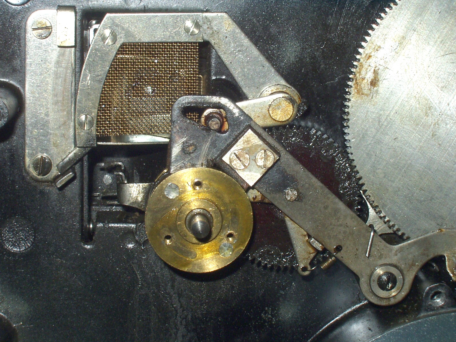
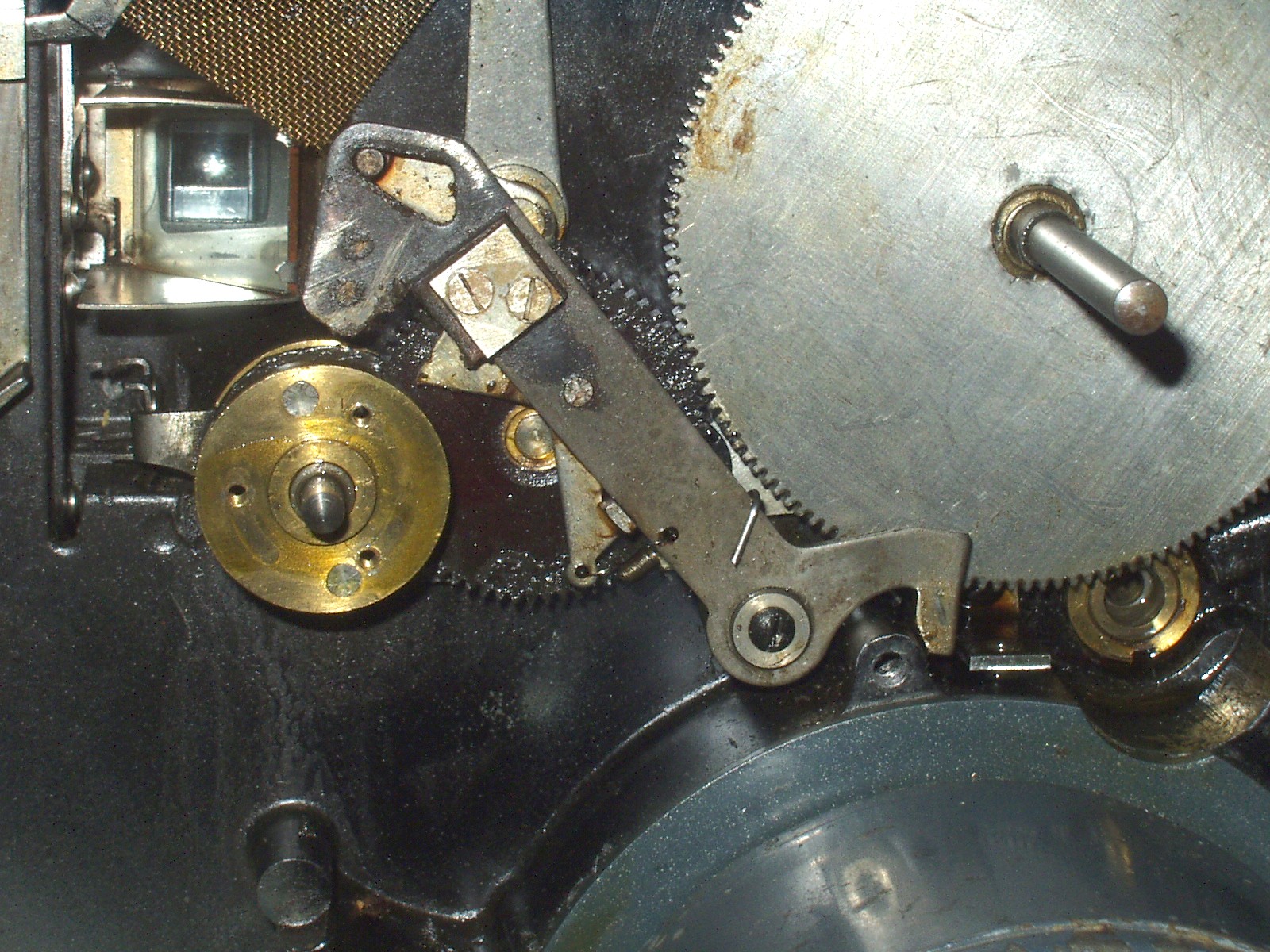
First is a general shot of the mech, showing not just one but two fibre gears. The sprung arm just left of the upper fibre gear has swung down to cover a bearing for the shutter (see pic 2. There is another, adjustable, bearing point in the rear cover). The felt pad on this arm rides clear of the rim that surrounds the gear until a notch triggers a stop; the pad then falls (spring-assisted) to brake the shutter. The gear on the shutter engages with the upper fibre gear as part of the train that delivers the step-up in speed. A significant difference which is not perhaps immediately obvious is the pivot for the arm that runs from below the big gear to the cam shaft. In the earlier DAs, this pivot was mounted directly onto the chassis. Here it is instead mounted onto another, shorter arm, which is then itself pivoted on the chassis. This shorter arm has a spring from its LH end across behind the scissor thing, but the arm is not connected to this in any way. I am at a loss to explain either the additional arm or the scissor thing. The felt pads do not appear to be linked to anything else which might, as I had half expected, apply them as brakes when the mech stops; they seem to be in contact all the time. I do not understand the function of the shorter arm; what it does (in run mode, not notch stop as in the pic) is to shift the position of the longer arm in such a way that the stud on the gauze screen, which sits in the shaped hole in the head of the arm, moves across from one side to the other. The lower end of the arm, which contacts the stirrup, also moves, but I do not see what either action achieves. Anybody know?
I am fairly confident the main problem is with distortion of the back plate. I have tried leaving the machine going in project mode as I insert the various screws; if I tighten them the mech slows or even stops. I can't really see a way of fixing this, tho' I think it will work well enough with the screws only gently tightened.
Timing the shutter is a pain - each of the many times I have removed the back plate to try yet another approach, the shutter falls out and timing is lost. I need to make a final adjustment so that I can make an empirical test of whether the shutter stops without blocking the gate, or the frequency with which one needs to adjust the inching knob to see a title.
I had to take the rear gate out because the notching mech was stuck, due presumably to the rust you can see, so I thought I would show you the complex system of arms that links the various bits of the notching mech. Complicated and fiddly (and that assumes you can even figure out how to remove the gate in the first place).
8th May
I have now separated the Bolex multi-gauge material to pages for the DA/PA and the G series (plus the P). I have put various additional text and pix on the DA page, not all of which have appeared here.

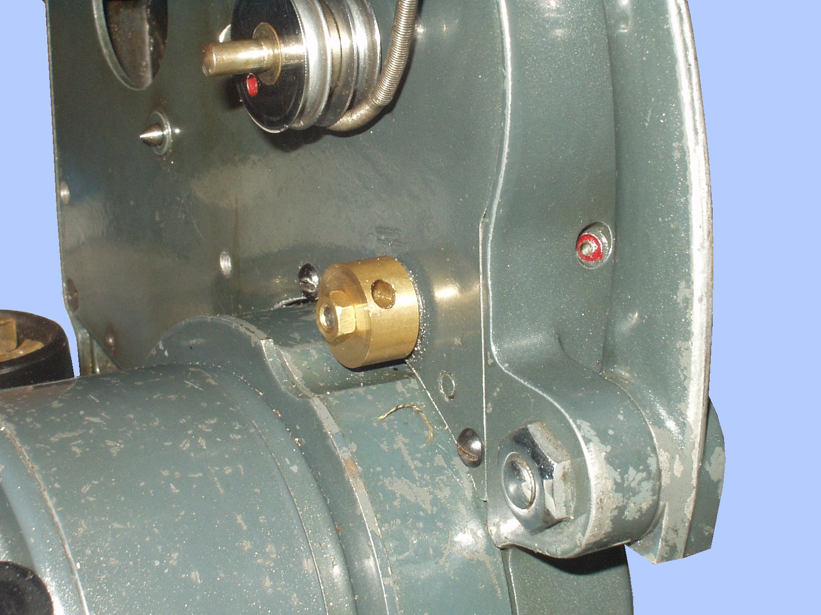


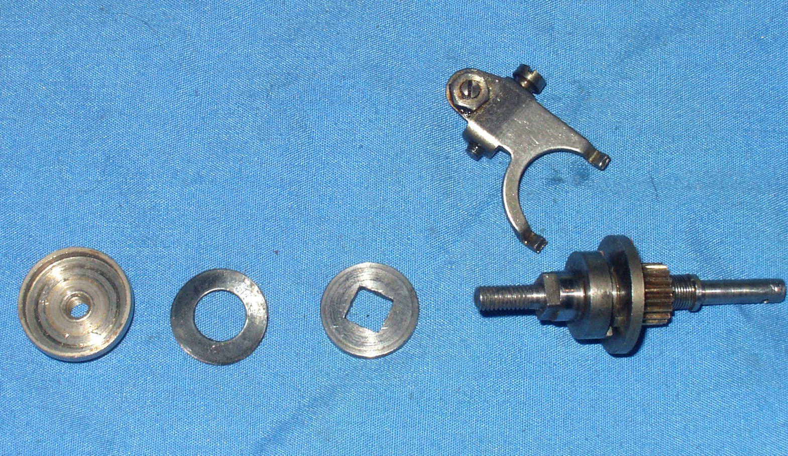
These pix show my new special nut and pulley on the second DA, plus pix of how these machines should really look. Note my pulley is slightly larger than the original, not for any particular reason. The special nut is somewhat smaller in diameter. I made it this way as I had a piece of brass about the right size and with that hole that passes thru the side of the nut without touching the central bore. This enables me to use a tommy bar thru the hole rather than a second spanner. I have found that the tightening of the special nut and locknut is both critical and difficult. It should NOT be done with a pair of pliers. You need 2 spanners, but one at least needs to be quite thin. If it ent, it will overlap onto the other nut and interfere with the locking. My new version does away with this problem. But it is essential to tighten the special nut by hand only; it should reach a definite stop and should be finger-tightened against this. When adding the lock-nut, do not allow the special nut to move; let the lock-nut do all the work. One snag I have found is that the sprung washer has an oversize bore and can protrude outside the special nut and get jammed against the square-holed washer. If this happens, the set-up won't work. Another point to watch in re-assembly is the pivot bolt which holds the stirrup. The bolt is only threaded right at the bottom, with the smooth section passing thru "brackets" at the top AND the bottom of the stirrup. It is regrettably easy to tighten the bolt without ensuring it has passed thru the lower bracket properly, or to get the bolt cross-threaded. If the bolt is anything other than free-turning until fully seated, it may indicate cross-threading, which could do serious damage to the mech.
3rd May
I have continued to wrestle with the Bolex DA. Another little trick it has manifested is to move the mech along in a desultory way without actually engaging fully. It has also now developed a tendency to speed up considerably for no apparent reason while running normally.
If you look again at pic 2 below, note the little collar next to the half of the clutch that includes the pinion gear. This collar limits the (leftward) travel of the pinion and clutch element. The other ( left hand) half of the clutch has a recess which fits over the collar when the clutch is engaged. When the stirrup moves the pinion back against the spring, the LH half stays still and the clutch disengages. However, I have discovered that the collar has been damaged and is no longer in the right place. If you look closely, you can see the end of the taper pin in the collar that fixes it to the shaft. However, you can also see the pin in the shaft itself - somehow the pin has been sheared right off and the collar has moved to the right. This has reduced the travel of the spring and also means that when tightening the dished special nut, it moves in too far; this may be part of the reason for the jamming problem. I am not terribly sure quite what has worked or why, but I have now ended up fitting the new pulley, the thinner square-holed washer AND a new collar with a tiny grub screw to hold it in place. This seems, for the moment, to work, tho' there is still the issue of sudden surges of speed.
I am not really sure what counsel to give to anyone facing problems with the notching mech. I think it is probably important not to over-tighten the special nut - this might be what has broken the taper pin, although I suspect some sort of blow or dropping of the machine is more likely. On the other hand, if it is not tight enough, the sprung washer will not transmit the drive to the square-holed washer. There seems to be a definite point where the special nut reaches a "stop"; this may or may not be something to do with the length of the screw thread at the LH end of the shaft and the smooth section that follows. It also seems to me - I have a second DA on the bench, too - that there are differences of detail between machines - the second has a much stronger spring on the notching shaft.
Sorry not to be more definite - if anyone has anything they can add, I'd be glad to hear it.
30th April
I have been fiddling with a Bolex DA that has been behaving oddly. It apparently runs for a bit, then slows down and stops. And I cannot figure out what is going wrong; everything I have tried so far simply does not work. Let me show you the notching mech, which seems to be at the root of the problem.



Pic one shows the heart of the notching mech; the RH end carries the pulley which takes the belt drive from the motor. Note the hole for the taper pin which fixes the pulley to the shaft. This shaft fits into the bearing hole best seen lower right in pic 7. At the RH side on the shaft is a spring held against a pinion/dog clutch assembly by a fixed collar; the pinion gear and the half dog-clutch can move a small distance to the right until the spring is completely compressed, but is prevented from moving in the opposite direction other than to allow the spring to de-compress to its "open" position The gear/clutch assembly is free to rotate on the shaft as well as move lengthways.
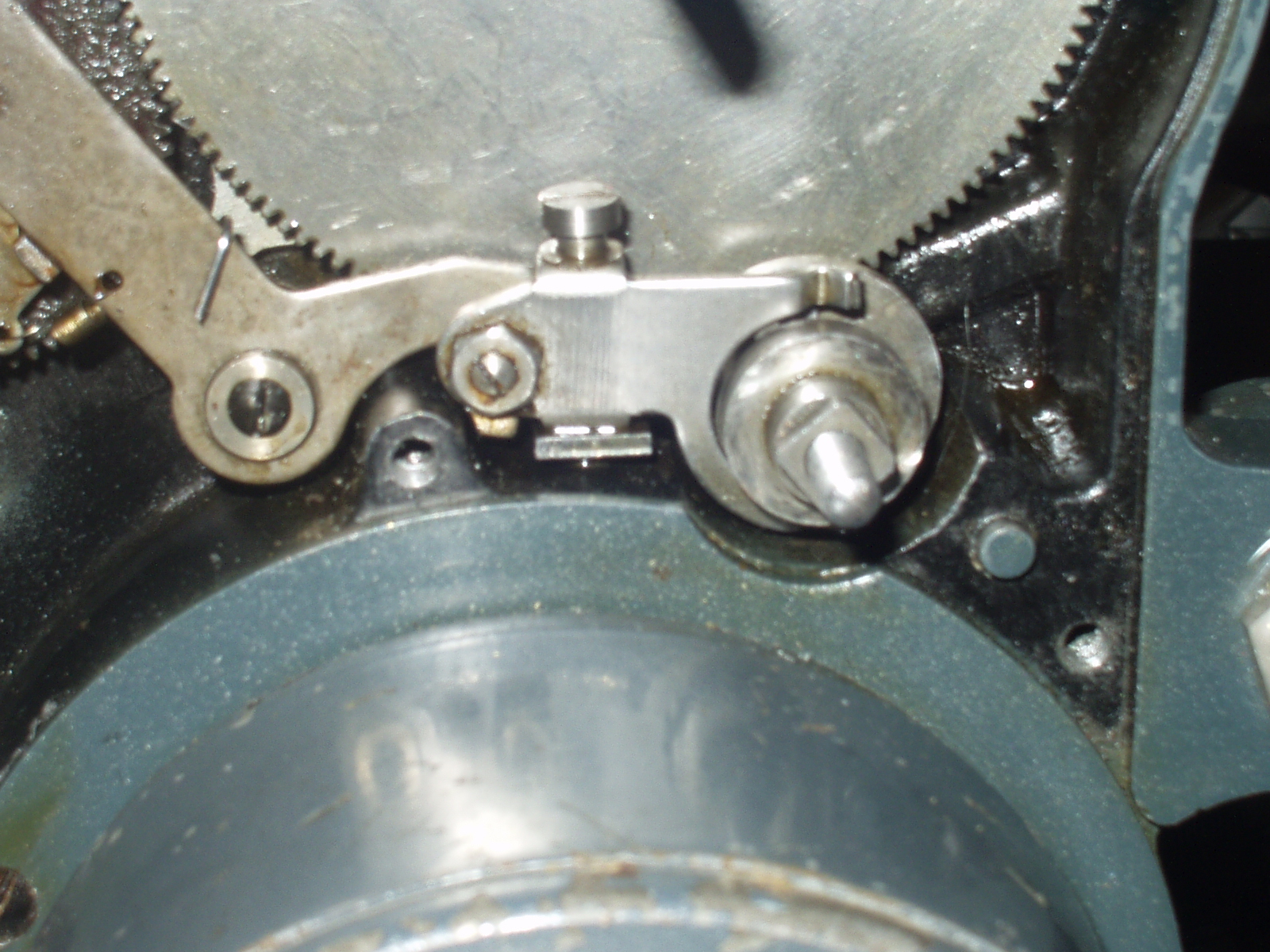
Pic 2 adds the other half of the dog-clutch. Its correct position is in full engagement with the other half of the clutch as in pic 3, but it is otherwise loose on the shaft.. The pinion/clutch assembly can move against the spring when pushed by the stirrup shown in pix 3 & 4; this dis-engages the clutch and so stops the projector. This is because the drive to the projector is from the pinion to the large gear seen in the last 3 pix. If I have explained clearly enough above, it will be seen that the pinion, being free to move on the shaft, cannot drive the big gear without some additional mechanism. Pix 3 & 5 show how this is done - this bit does my head in. A washer with a square hole fits over the square end of the LH part of the dog clutch, but only after the side cover of the machine has been replaced. A sprung washer is brought to bear on the square-holed washer by the special nut, the two sides of which are seen in pix 3 & 5- one side has a recess for the sprung washer and the other has flats for a spanner. The special nut is tightened, forcing the sprung washer into contact with the square-holed washer and is then held in place by a conventional nut, acting as a lock-nut. So, if I have this right, the drive passes from the motor to the pulley on the end of the notcher shaft. The shaft rotates, taking the lock-nut and the sprung and square-holed washers with it, so turning the outer half of the dog-clutch, which then engages with the other side of the clutch and rotates the pinion which drives the big gear. Moving the pinion against the spring dis-engages the dog-clutch and stops the mech.
This latter part of the mech is seen in the final 3 pix. Pic 2 on the bottom row shows the notcher shaft in its bearing, with the outer half of the clutch in place. The stirrup is loosely mounted in place to show how it works. Pix 1 and 3 show the mech in, respectively, still frame and normal projection modes. When a notch activates the mech, the hammer-shaped arm is pulled down by a spring, and a brake-pad brings the shutter to a stop. The RH end of the hammer arm has a shaped portion which, as it rises in response to the other end dropping, pushes the stirrup so as to separate the two halves of the dog clutch and disengage the drive.
What seems to happen is that the special nut tightens up so much it causes the entire shaft assembly to stiffen and bind, causing the mech to stall, or else the lock-nut is loosened, the special nut unscrews and the drive is lost. What I cannot suss is why. I have tried making a new, thinner square-holed washer, adding an additional spacer between the fixed collar and the bearing, even making a new pulley secured by grub screws so I can leave some slack between the drive pulley and the mech body (can't do this with the taper pin). Also, the shaft seems to behave sometimes as tho' it is bent, making the pulley rotate eccentrically. Shall have to keep working on it.



23rd April
Mikael Barnard has acquired a Kodascope Model A and brought it along for us to play with. Got some film thru it with no trouble, but it sounds a bit clunky mechanically, which I suppose needs investigating, tho' obviously it's not a machine one is going to use every day.


The "spool boxes" are a bit mysterious, as there is nothing to show they ever were boxes. I have marked an odd scalloping in a couple of the pix which I spose could have been for hinges, but there's nothing to support this speculation. This machine also has the later 50v 200w lamp, which is interesting from the point of view of the chronology of the machine's development, as one would not (I am told) expect boxes with the later lamp.
Pix 4 and 5 show the complex arrangement for (inter alia - I do not claim to understand everything that is going on here) dis-engaging the motor from the mech - it pivots against a spring, bringing the motor's rubber wheel in or out of contact. The long lever coming over the top of the spool box is a remote control, not needed in the later model I have, which has no spool boxes. Hard to see what the idea was, as 16mm film, like 9.5, was on safety stock. But just consider the huge contrast between this, almost contemporaneous, machine and the PathBaby. They don't seem to be from the same world, tho' in my view the Kodascope is way over the top for what it has to do; there is an array of gears to die for inside - but for what? I have sometimes wondered why some if not all 16mm projector manufacturers made their machines as complex as they did - it's not going to do much to overcome the inherent limitations of both picture and sound at the narrow-gauge level.
Have been looking at a Bolex SM8 sound machine. Here are a few shots.


As you can see, it suffers as so many did from a capacity limited to 600' because the take-up is
incorporated into the main body. Top marks, tho', for high output from a 12v 100w lamp and for an
easily removable amp. In pic 3 you can see there is a multi-way plug, a pair of wires in a black
sheath and two green wires, which are all that need removing to separate the amp out entirely.
A slightly curious feature is that the fan (pic 2) is not integral at all, but in the back cover. And
it blows out direct thru the top of the projector. This must mean that, instead of cooling by
directing air at where the heat is, this fan acts as an exhauster, and drags air from the entire
projector cavity.
I have been fortunate in that it has come complete with its own carrying case, which contains
an extension speaker and included is a mains lead - an unusual small 2-pin with earth on the outside.
The speaker connector is also idiosyncratic, a four-pin DIN plug. There is an instruction book,
but it seems to be a copy of one for a different version. No doubt the case is why the machine
has remained in remarkably good condition.
11th February
Have added a few more pages of Pathescope Monthlies, including the March 1941 issue, the last emission
from Pathescope until the News Sheet of May 1949.
9th February
Here are some pix of the machine and motor I have been speaking of the last few weeks. The machine has
been re-painted in grey, and is the original home of the grey motor with mazac damage to the front cap.
That motor is now awaiting a new cap. This motor is the one I was having trouble with not driving the
mech and sent back to the rewinders. They have fiddled and added a slightly higher-rated capacitor ( 12mF
as opposed to the original 10) and it now works fine, at 110v. This motor had a bad paint job so I decided
to go mad and clean all the paint off, having already noticed that the main casing was brass and would
make a nice contrast with my new alu end cap.


As you can see, the grey paint is also peeling off (the imported motor was black). The contents of the
base of this machine are much simplified, so it would be easier than usual to completely strip down
and re-paint. Clearly, something special like an etch primer is needed to make the paint stick.
This mech belongs with the amp I have been telling you about. I have now made a further attempt
on it, replacing the main 50mF + 50mF capacitor with a sprauncy new one. All I managed to achieve
was a cloud of smoke and the total destruction of two resistors connected to the rectifier valve.
At least, that's what I can see - there may be other damage! I am clearly cursed as far as electronics
are concerned. As well as ignorant.
5th February
Also bin working on a Vox where the mech is stiff, but for good reasons. The main drive shaft seems to
be out of true - the gear wheels can be seen to move significantly in the horizontal plane as they revolve.
I also found that the Woodruff key (which links the gear assembly firmly to the drive shaft) was missing.
In the process of fiddling with this I discovered something I had not previously noticed - the threaded
part of the gear assembly used to move the gears to and fro is separate from the body of the assembly,
and is held in place by a grub screw thru the threaded section and down into the body of the gear
assembly.
The claw has a much stiffer spring than I am used to seeing on the Vox, and there is one point in the
claw cycle where the claw and spring seem to be in just the wrong place and simply jam. It's fine if
you back off a bit and try again, or if momentum carries it thru, so it's really an issue for inching and
starting, as it seems OK once moving. I am hoping to get it to a state where it will run satisfactorily.
Or I may try a weaker spring or even no spring at all - I have known machines to run without. I remain
a bit confused as to the function of the spring, especially as it seems to resist the downward, working
stroke and to aid the return of the claw to the top for the next stroke.
3rd February
At Argenteuil 2012, I had the chance to buy a Triplico to compare with my existing Peerless version.


First is a small pic I acquired somewhere, showing a machine matching the one I just got.
However, I had expected something more like the image in pic 3. So still some mystery to be solved.