BOLEX DA, PA, C
Bolex made a number of machines for more than one gauge; the DA/PA type, which could also show 9.5 notched films, and the "G" series in numerous guises.


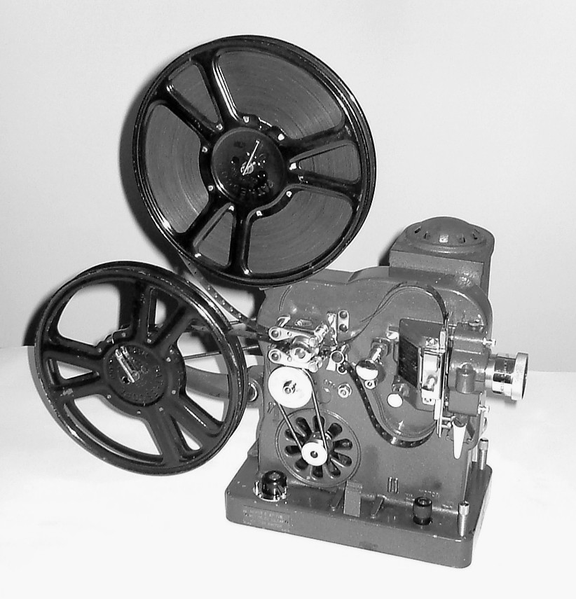
Here, courtesy the PPT, is a very early Bolex of the PA/DA shape. This is a Model C; when I saw it, there were no 9.5mm parts and I assumed it was 16mm only. Note the ornate logos, the pushmi-pullyu still frame device (altho' I suspect now it is incomplete), the switch (far more use than the direction change lever we got later), the one-piece lamphouse with simple pin fixing and ornate top. I think that, with the front adjuster leg out of the way, the lamphouse will swing open, maybe to keep light from the film until you were ready As you will see later, there could be a "skirt" missing from the bottom of the lamphouse. Less obviously, there are no moveable sprocket retainers. The rollers are held in place with nuts, hidden behind a large gearwheel inside the mech. Which means that to clean them, I had to remove the pin on the sprocket shaft, unscrew the grub-screw in the sprocket, remove the lamphouse and the back of the projector and slide out the large gear wheel on the other end of the sprocket shaft. It now runs bootiful, tho'. I also noted that it has a mesh filter much like the heat filter on later machines, which operates centrifugally.
The shutter (2 blades only) is much thicker metal than the later paper-thin jobbies. The rewind handle is removable but, remarkably, has survived. I will deal with this early type of machine at greater length below.
This Bolex PA (9.5 only) has been adapted to halogen lighting, 900ft spool capacity and separate switching for lamp and motor. These machines, and the dual-gauge DA, give about as good as you can get from notched films, but you do have to manually re-start after each notch, whereas the Baby and Lux do this automatically. Can a boy have too many Bolex DA's? The problem is, only one of them has the 9.5 parts, so if anyone has some spare......
I recently found that I had a spare 9.5 gate, sprocket and one spool spindle for a Bolex DA. I managed to machine a spindle from a spare G3 one, which is very similar but longer. The gate was more problematic. I had not previously realised that the 9.5 gate differs as between the PA and the DA. The PA slots to clear the 16mm claw are quite a bit lower down than those for the DA. The gate I had found was a PA so I had to lengthen the slots. For some reason, it didn't have the cut-out in the side of the gate to allow the notching mechanism to engage, so I had to machine this, too. Why is nothing ever simple?
Here are a couple of sets of instructions for this range of machines. One is a pdf to avoid me (and you) having to toggle thru a number of separate pages.


DAInstrsc.pdf
There was even a sound version......


----------------------------------------------------------
Discovering interesting facts about the Bolex DA. I can now see there were (at least) two models, one like the PA but the other with a large rounded protrusion on top. This appears to cater for a much larger shutter. The only one I've seen is in this pic Dino sent me.

Ken Finch has referred me to Gerald McKee's projector book for the story on the Bolex DA and its shutter. I think I have now got the story straight in my head. The original PA and DA did not have the rounded top and used an ordinary 2-blade shutter. The problem with this seems to have been flicker, tho' I must say it is not something I have noticed. Bolex, however, introduced the 1937 Model, which had a larger diameter shutter, rotating much faster, giving three obscurations per frame, so eliminating flicker. However, the faster shutter made more noise and, because it had a big shutter with a single "hole" of about one quarter of the total, tended to stop with titles obscured, requiring manual intervention. At the same time, a more powerful cooling fan was fitted, enabling a 400w lamp to replace the earlier 250w. Naturally, people tended to use the 400w lamp in earlier models which didn't have the improved cooling, hence the usual scorched lamphouse sported by most machines. Better than scorched titles, I suppose.
-----------------------------------------------------------------------------------
Have now moved on to a Bolex DA, 1937 Model wiv the bigger, faster shutter, bigger cooling fan ect. In accordance with the best principles of projector storage and the relevant British Standards, this machine has been kept in conditions of unregulated cold and damp and had in consequence seized up solid. Aluminium castings show that white "bloom" in places and some steel parts, especially the more delicate, have rusted. There appears also to be distortion of the rear plate/mech cover which, as it journals a number of shafts, is rather serious and probably accounts for most of the seizing up.


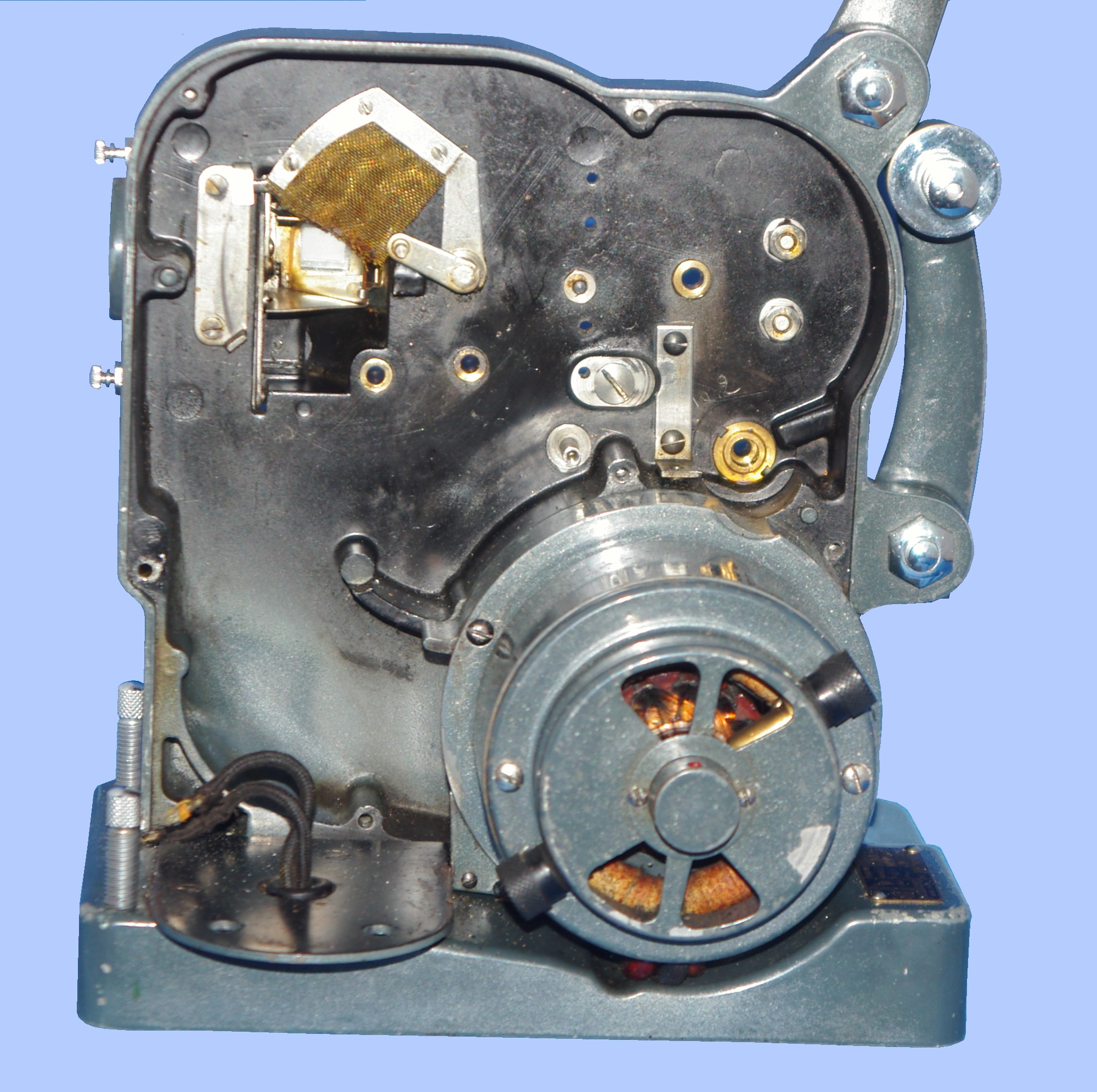
First is a general shot of the mech, showing not just one but two fibre gears. The sprung arm just left of the upper fibre gear has swung down to cover a bearing for the shutter (see pic 2. There is another, adjustable, bearing point in the rear cover). The felt pad on this arm rides clear of the rim that surrounds the gear until a notch triggers a stop; the pad then falls (spring-assisted) to brake the shutter. The gear on the shutter engages with the upper fibre gear as part of the train that delivers the step-up in speed. A significant difference which is not perhaps immediately obvious is the pivot for the arm that runs from below the big gear to the cam shaft. In the earlier DAs, this pivot was mounted directly onto the chassis. Here it is instead mounted onto another, shorter arm, which is then itself pivoted on the chassis. This shorter arm has a spring from its LH end across behind the scissor thing, but the arm is not connected to this in any way. I am at a loss to explain either the additional arm or the scissor thing. The felt pads do not appear to be linked to anything else which might, as I had half expected, apply them as brakes when the mech stops; they seem to be in contact all the time. I do not understand the function of the shorter arm; what it does (in run mode, not notch stop as in the pic) is to shift the position of the longer arm in such a way that the stud on the gauze screen, which sits in the shaped hole in the head of the arm, moves across from one side to the other. The lower end of the arm, which contacts the stirrup, also moves, but I do not see what either action achieves. Anybody know?
I am fairly confident the main problem is with distortion of the back plate. I have tried leaving the machine going in project mode as I insert the various screws; if I tighten them the mech slows or even stops. I can't really see a way of fixing this, tho' I think it will work well enough with the screws only gently tightened.
Timing the shutter is a pain - each of the many times I have removed the back plate to try yet another approach, the shutter falls out and timing is lost. I need to make a final adjustment so that I can make an empirical test of whether the shutter stops without blocking the gate, or the frequency with which one needs to adjust the inching knob to see a title. I had to take the rear gate out because the notching mech was stuck, due presumably to the rust you can see, so I thought I would show you the complex system of arms that links the various bits of the notching mech. Complicated and fiddly (and that assumes you can even figure out how to remove the gate in the first place).
I find I have done a lot on the Bolex notching mechanism and how to make it work, so I decided this topic needed a page on its own, as Page 2.
PLEASE NOTE: All the pictures on this page are of the old type, opening one at a time and closing only with the backspace arrow at top left of the page. ONLY those with a little magnifying glass in the bottom left-hand corner of the thumbnail have their own button actually on the enlarged picture. Some of these are linked in groups.
I have been fiddling with a Bolex DA that has been behaving oddly. It apparently runs for a bit, then slows down and stops. And I cannot figure out what is going wrong; everything I have tried so far simply does not work. Let me show you the notching mech, which seems to be at the root of the problem.
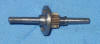



Pic one shows the heart of the notching mech; the RH end carries the pulley which takes the belt drive from the motor. Note the hole for the taper pin which fixes the pulley to the shaft. This shaft fits into the bearing hole best seen lower right in pic 7. At the RH side on the shaft is a spring held against a pinion/dog clutch assembly by a fixed collar; the pinion gear and the half dog-clutch can move a small distance to the right until the spring is completely compressed, but is prevented from moving in the opposite direction other than to allow the spring to de-compress to its "open" position The gear/clutch assembly is free to rotate on the shaft as well as move lengthways.
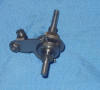
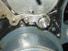
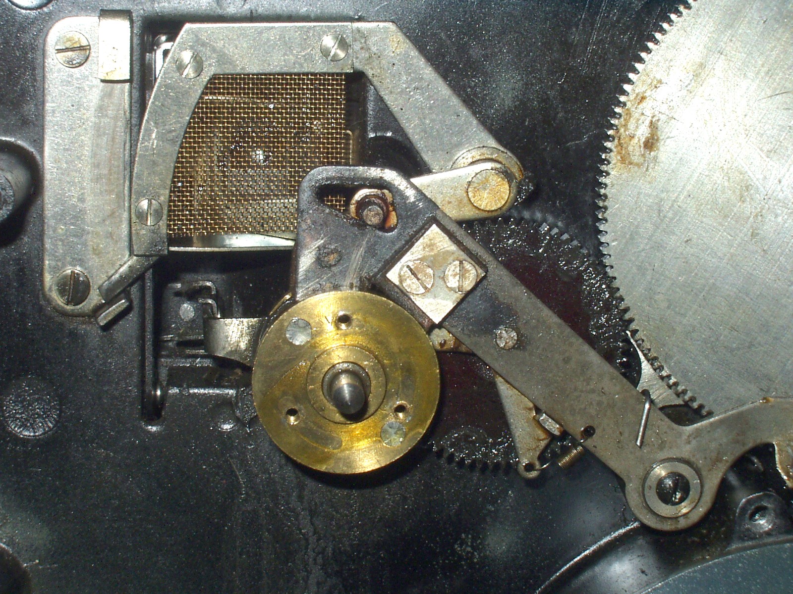
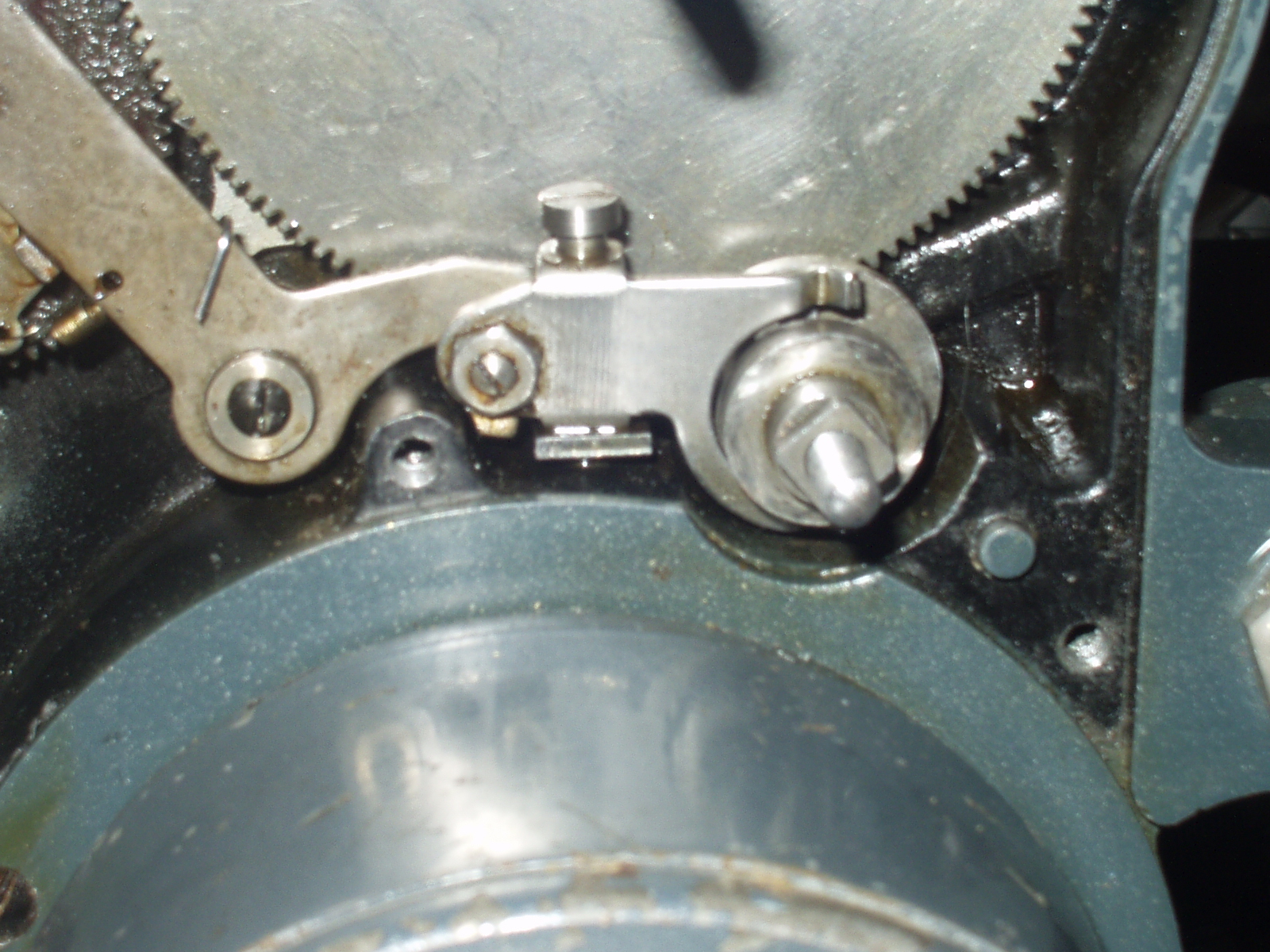
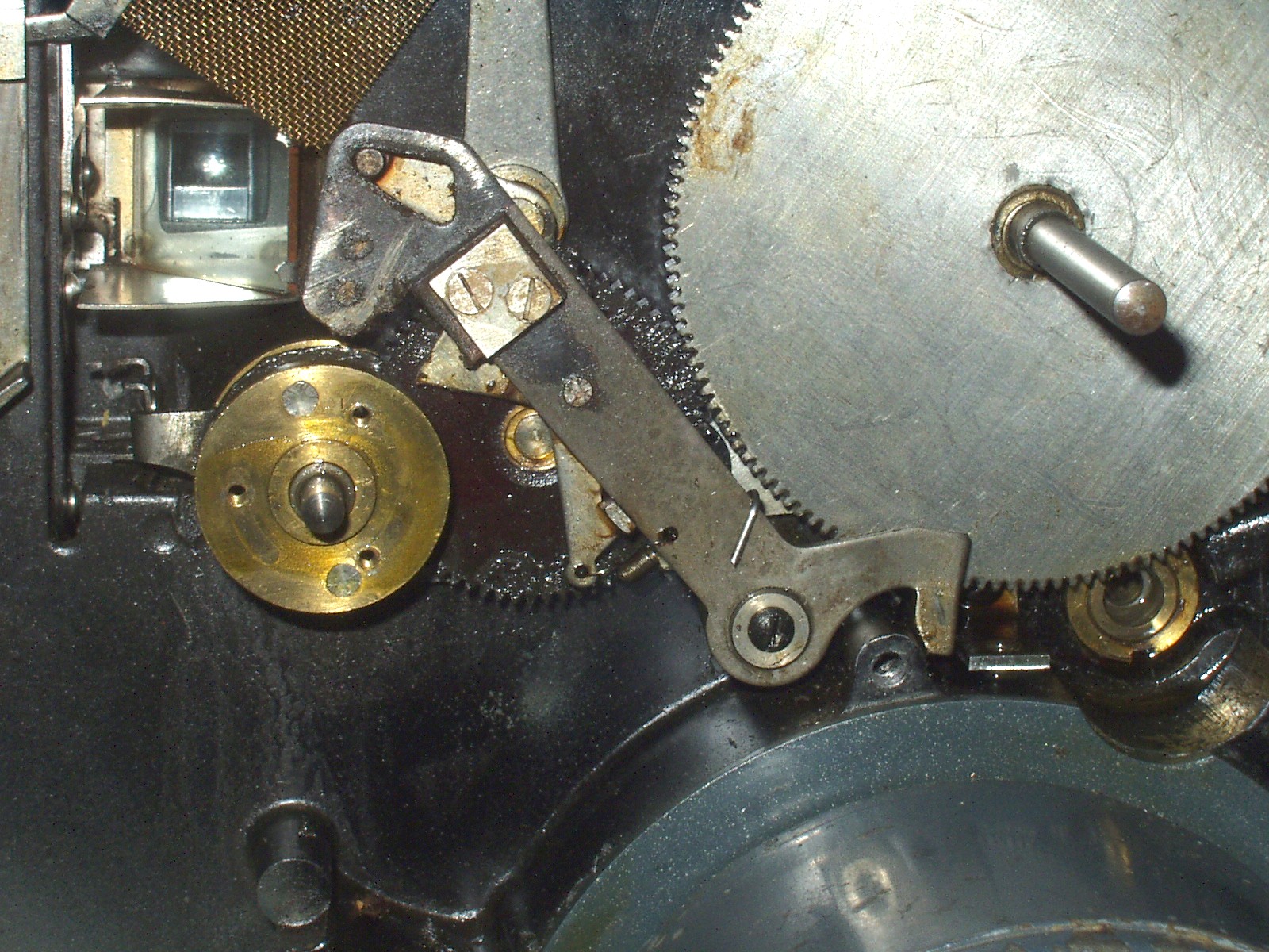
Pic 2 adds the other half of the dog-clutch. Its correct position is in full engagement with the other half of the clutch as in pic 3, but it is otherwise loose on the shaft.. The pinion/clutch assembly can move against the spring when pushed by the stirrup shown in pix 3 & 4; this dis-engages the clutch and so stops the projector. This is because the drive to the projector is from the pinion to the large gear seen in the last 3 pix. If I have explained clearly enough above, it will be seen that the pinion, being free to move on the shaft, cannot drive the big gear without some additional mechanism. Pix 3 & 5 show how this is done - this bit does my head in. A washer with a square hole fits over the square end of the LH part of the dog clutch, but only after the side cover of the machine has been replaced. A sprung washer is brought to bear on the square-holed washer by the special nut, the two sides of which are seen in pix 3 & 5- one side has a recess for the sprung washer and the other has flats for a spanner. The special nut is tightened, forcing the sprung washer into contact with the square-holed washer and is then held in place by a conventional nut, acting as a lock-nut. So, if I have this right, the drive passes from the motor to the pulley on the end of the notcher shaft. The shaft rotates, taking the lock-nut and the sprung and square-holed washers with it, so turning the outer half of the dog-clutch, which then engages with the other side of the clutch and rotates the pinion which drives the big gear. Moving the pinion against the spring dis-engages the dog-clutch and stops the mech.
This latter part of the mech is seen in the final 3 pix. Pic 2 on the bottom row shows the notcher shaft in its bearing, with the outer half of the clutch in place. The stirrup is loosely mounted in place to show how it works. Pix 1 and 3 show the mech in, respectively, still frame and normal projection modes. When a notch activates the mech, the hammer-shaped arm is pulled down by a spring, and a brake-pad brings the shutter to a stop. The RH end of the hammer arm has a shaped portion which, as it rises in response to the other end dropping, pushes the stirrup so as to separate the two halves of the dog clutch and disengage the drive.
What seems to happen with this machine is that the special nut tightens up so much it causes the entire shaft assembly to stiffen and bind, causing the mech to stall, or else the lock-nut is loosened, the special nut unscrews and the drive is lost. What I cannot suss is why. I have tried making a new, thinner square-holed washer, adding an additional spacer between the fixed collar and the bearing, even making a new pulley secured by grub screws so I can leave some slack between the drive pulley and the mech body (can't do this with the taper pin). Also, the shaft seems to behave sometimes as tho' it is bent, making the pulley rotate eccentrically.
Another little trick it has manifested is to move the mech along in a desultory way without actually engaging fully. It has also now developed a tendency to speed up considerably for no apparent reason while running normally.
If you look again at pic 2 above, note the little collar next to the half of the clutch that includes the pinion gear. This collar limits the (leftward) travel of the pinion and clutch element. The other ( left hand) half of the clutch has a recess which fits over the collar when the clutch is engaged. When the stirrup moves the pinion back against the spring, the LH half stays still and the clutch disengages. However, I have discovered that the collar has been damaged and is no longer in the right place. If you look closely, you can see the end of the taper pin in the collar that fixes it to the shaft. However, you can also see the pin in the shaft itself - somehow the pin has been sheared right off and the collar has moved to the right. This has reduced the travel of the spring and also means that when tightening the dished special nut, it moves in too far; this may be part of the reason for the jamming problem. I am not terribly sure quite what has worked or why, but I have now ended up fitting the new pulley, the thinner square-holed washer AND a new collar with a tiny grub screw to hold it in place. This seems, for the moment, to work, tho' there is still the issue of sudden surges of speed.
I am not really sure what counsel to give to anyone facing problems with the notching mech. I think it is probably important not to over-tighten the special nut - this might be what has broken the taper pin, although I suspect some sort of blow or dropping of the machine is more likely. On the other hand, if it is not tight enough, the sprung washer will not transmit the drive to the square-holed washer. There seems to be a definite point where the special nut reaches a "stop"; this may or may not be something to do with the length of the screw thread at the LH end of the shaft and the smooth section that follows. It also seems to me - I have a second DA on the bench, too - that there are differences of detail between machines - the second has a much stronger spring on the notching shaft.
Sorry not to be more definite - if anyone has anything they can add, I'd be glad to hear it.
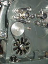


These pix show my new special nut and pulley on the second DA, plus pix of how these machines should really look. Note my pulley is slightly larger than the original, not for any particular reason. The special nut is somewhat smaller in diameter. I made it this way as I had a piece of brass about the right size and with that hole that passes thru the side of the nut without touching the central bore. This enables me to use a tommy bar thru the hole rather than a second spanner. I have found that the tightening of the special nut and locknut is both critical and difficult. It should NOT be done with a pair of pliers. You need 2 spanners, but one at least needs to be quite thin. If it ent, it will overlap onto the other nut and interfere with the locking. My new version does away with this problem. But it is essential to tighten the special nut by hand only; it should reach a definite stop and should be finger-tightened against this. When adding the lock-nut, do not allow the special nut to move; let the lock-nut do all the work. One snag I have found is that the sprung washer has an oversize bore and can protrude outside the special nut and get jammed against the square-holed washer. If this happens, the set-up won't work. Another point to watch in re-assembly is the pivot bolt which holds the stirrup. The bolt is only threaded right at the bottom, with the smooth section passing thru "brackets" at the top AND the bottom of the stirrup. It is regrettably easy to tighten the bolt without ensuring it has passed thru the lower bracket properly, or to get the bolt cross-threaded. If the bolt is anything other than free-turning until fully seated, it may indicate cross-threading, which could do serious damage to the mech.
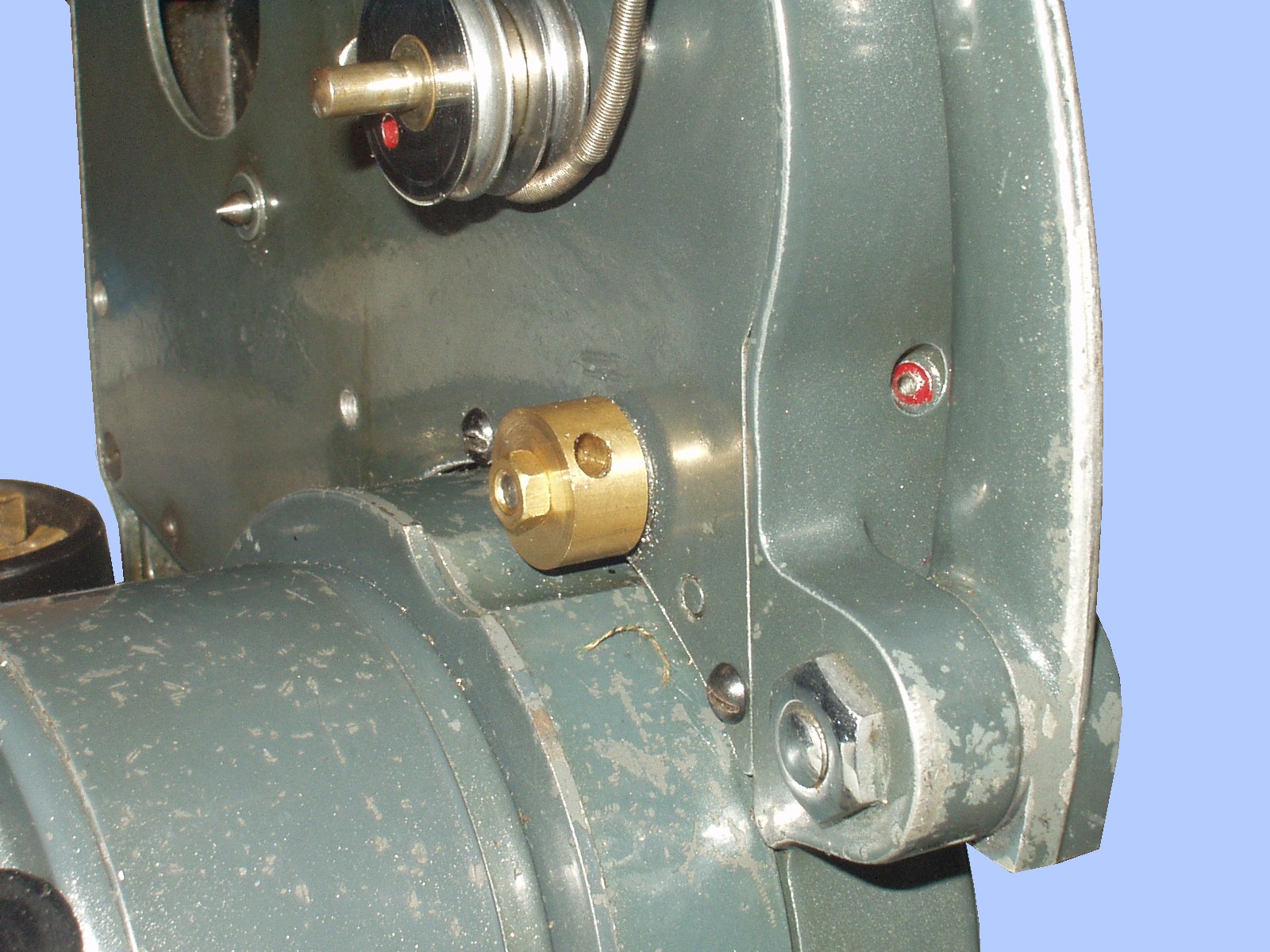
One of the trickiest parts of re-assembly is the torsion spring, see pic left. Look at the pivot just under LH side of the big gear and immediately above the motor case. One end of the spring is just visible above the pivot, the other end rests on the raised bit of casting immediately to the right. Trouble is, it has to be given a lot of twist to get this second end in place, at the same time as pushing the arm into place. Very fiddly. The spring is wrapped round a large spacer which is part of the pivot, and can be seen in the centre pic below. This spring seems able to get one of its coils between the end of the spacer and the machine, preventing the pivot arm from bedding in correctly - the screw tightens but locks the pivot solid until you can find a way to get the stray coil onto the spacer where it belongs. As you can see, it's actually pretty difficult to see to do this.
May 2014
I might, just might, have found a solution to the problems covered above with the notching mechanism.
I have been wrestling on and off for an age with a problem afflicting certain Bolex DA machines belonging to me and various friends. What happens is that, while the notching mech works fine with the side off, add the side and the mech jams, or fails to turn, or turns very slowly and lackadaisically with no real
force or conviction. I have formed a theory that, for reasons unknown, wear or some other problem has caused the side plate to interfere with the correct operation of the notching mech. The tricky bit required testing of the theory by making a copy of part of the mech with part of it extended so as to move it well clear of the side plate. The part in question is shown in this pic; the section I have made longer is marked in red. This part is one half of a dog clutch; in use it actually sits up against the ring, fixed to the shaft with a thru pin, that you can see just in front of the other part of the dog clutch. It is this latter part that moves, against the spring you can see, to operate the notching mech. The part I have copied rotates but does not move to and fro once set in place. Anyway, it seems to work, but I am sending the new part to a friend to test further.
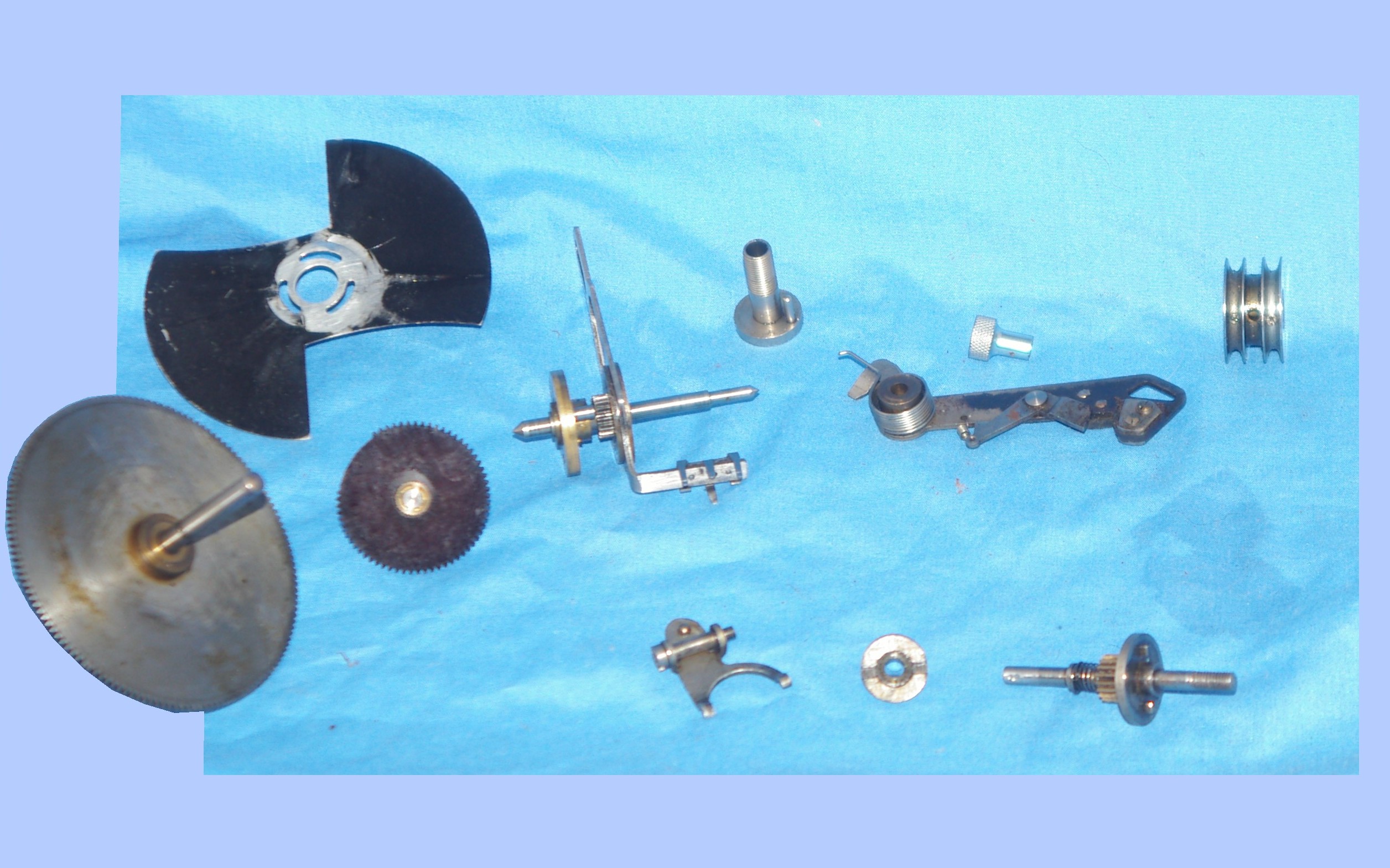
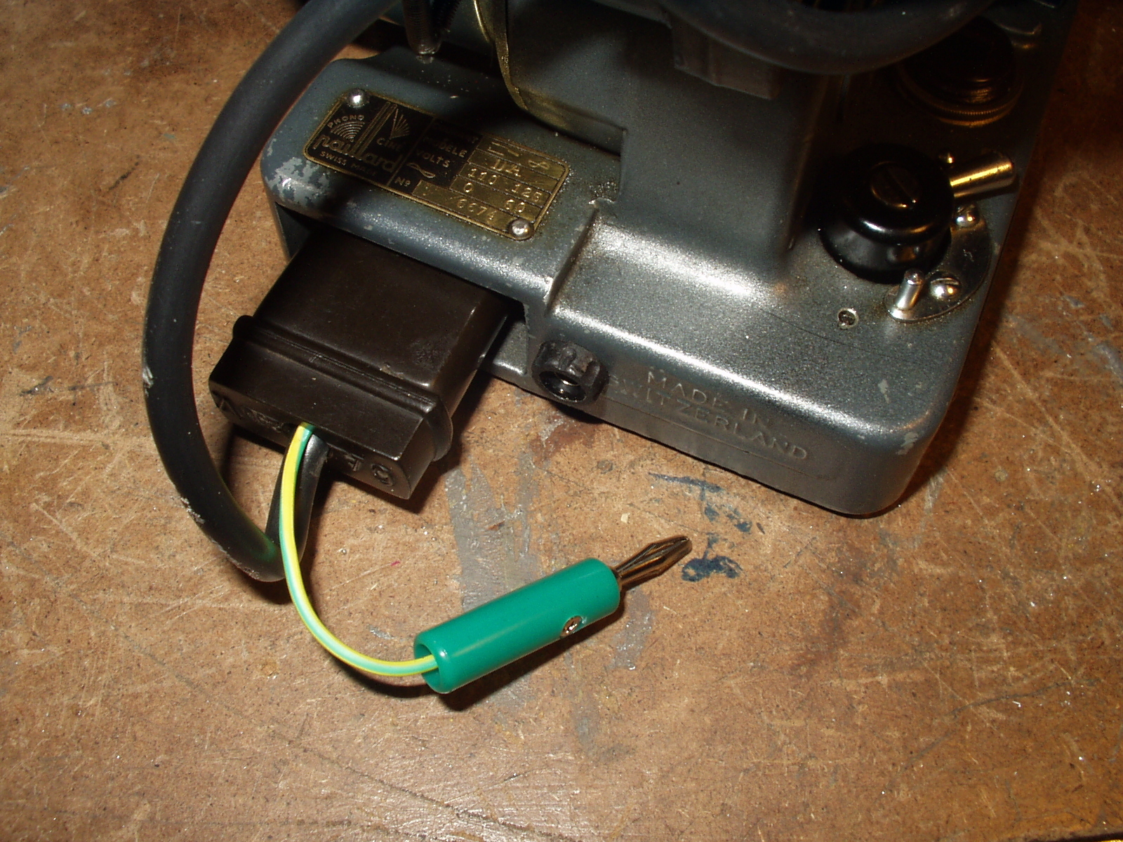
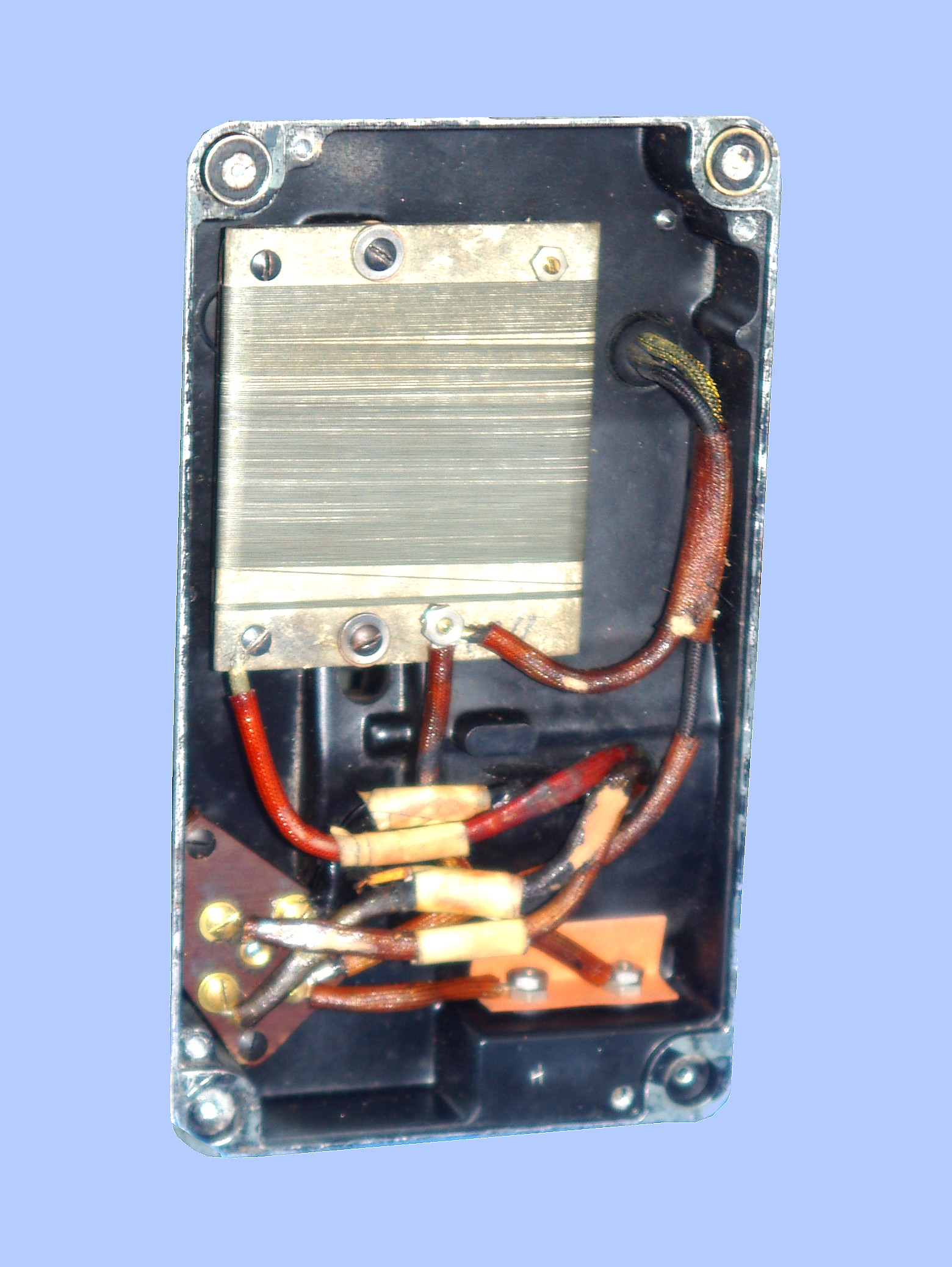
Here are some additional pix of the machine stripped down and parts, plus an earth I fitted to one machine - a rare case where I think changing the original discreetly is justifiable - and an underside view.


-------------------------------------------------
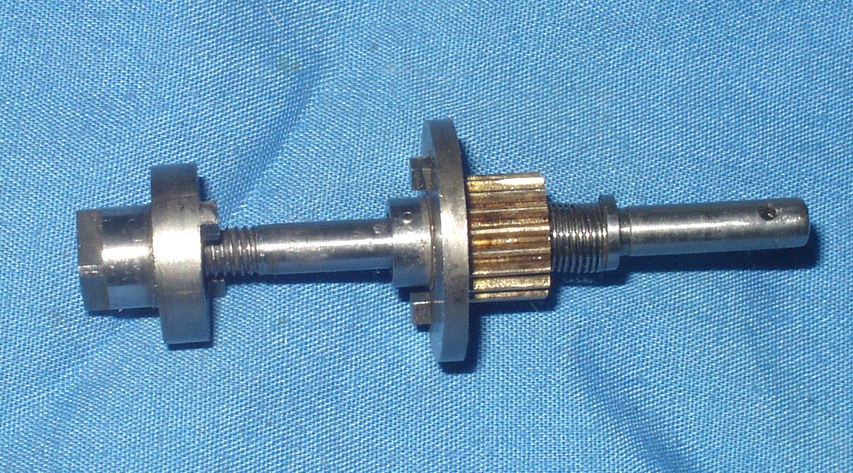
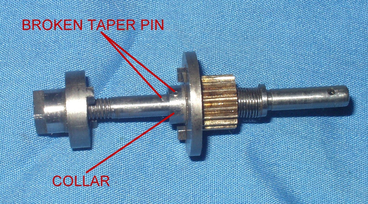
Yet more on the weird problems of the Bolex DA. A key part of the mechanism is shown here - it is the main drive shaft running from the pulley at the front of the machine which is driven by the motor, to the outer end at the back where the square washer etc fit.
The pic shows a broken one. What there should be is a collar like the one shown, ie a round thing like a donut, only about 3.2mm or so wide, which is fixed to the shaft by a pin that passes thru the collar, then the shaft and then into the collar again on the other side. Imagine the broken bits as shown all lining up, unbroken. It stops the part with the gear from moving too far to the left, and it stops the other half of the dog clutch, ie like the bit I made a copy of, moving more and more to the right and squashing the spring behind the gear so much that it starts to seize up the mech. And the collar has to fit within recesses in the 2 halves of the dog clutch (or maybe only 1 recess cant recall). If you extract this assembly from one of your machines all will become miraculously clear. I skirted around this idea before (see highlighted text a bit further up this page).
I increasingly think this is the root of all evil. The last busted machine I had was like this, I fixed it and lo! no problems!
---------------------------------------------------------------------------------------------------------------
I have had an enquiry from someone with a got-at Bolex DA who (brave man) is planning to make a new shaft for the clutch mech. I took a few pix and did some measuring, which I may as well add here.


The first row reinforces the importance of the small collar against which the spring holds the combination gear and dog clutch. This is held in place by a pin thru both sides of the collar via a hole in the shaft. It appears this pin is easily broken by over-tightening the external fixing. This arises essentially from a minor design flaw. To explain this. here are a couple of pix you may have seen before.


The fundamental basis of the notching mechanism is a dog clutch, the two halves of which can be seen in pic 1 above. The inner half is fixed to a gear, but both halves are free to rotate on the shaft. When a notch passes thru the gate, the stirrup seen top in pic 2 and in situ in pic 3 pushes the inner end of the dog-clutch against the spring and so out of engagement with the outer half. This cannot follow because it is stopped by the collar secured by a pin. In pic 5 of the top row you can see this pin protruding - infact, it can't do this in use as it would foul the dog clutch, so it has to be a flush fit.
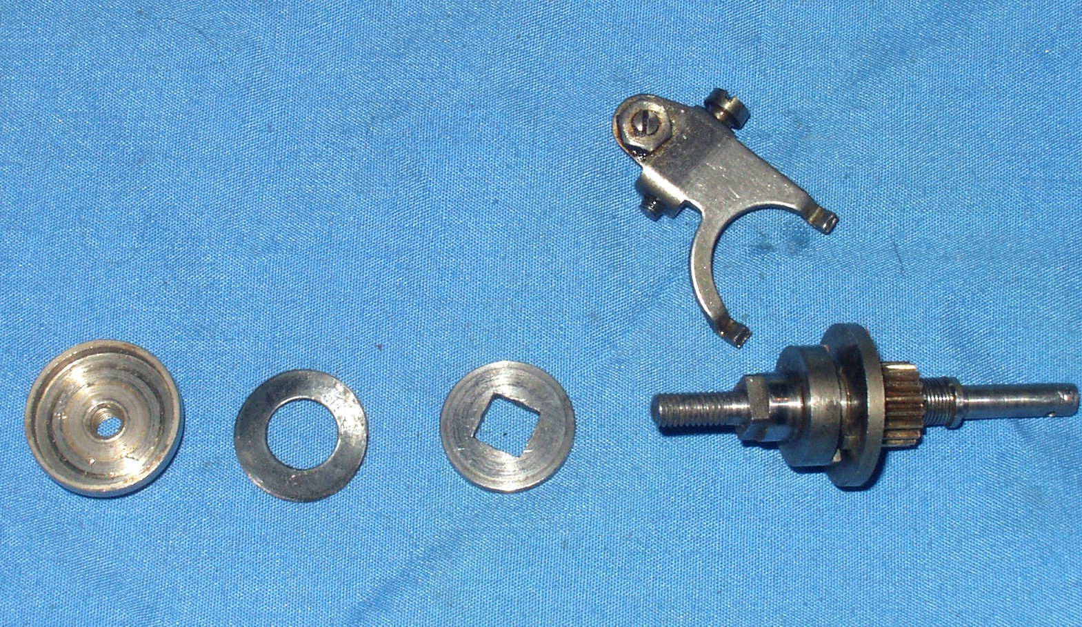
The outer part of the dog clutch has a square end which protrudes thru the back plate of the machine, and is then fitted with the square-centre washer seen in pix 2 and 4 above. Continuing to work outwards, next comes a spring washer (second from right in pic 4 above). This is a bit dished in shape so that when compressed it grips. This washer fits inside the dished cover (3rd from right in pic 4 and 1st left in pic 2, showing the two different sides). As can be seen in pic 4, this cover has two flats on its outer end, to assist in locknutting it against the final nut (left in pic 4). I think it is this process of locknutting that causes the problem - I am sure many people try to do it without two spanners, one of which needs to be unusually thin. Either the dished cover is over-tightened in the first place or during a bodged attempt at locknutting, which forces it up against the collar. Given that the dished cover is on a fairly fine thread, it can deliver a considerable force for relatively little effort, enabling it to break the pin. The entire thing is then disabled and at worse can cause the mech to jam up completely.
A Bolex DA Power Pack (Autumn 2014)
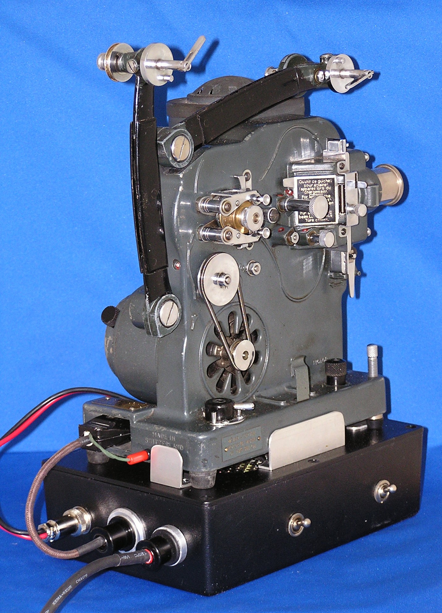
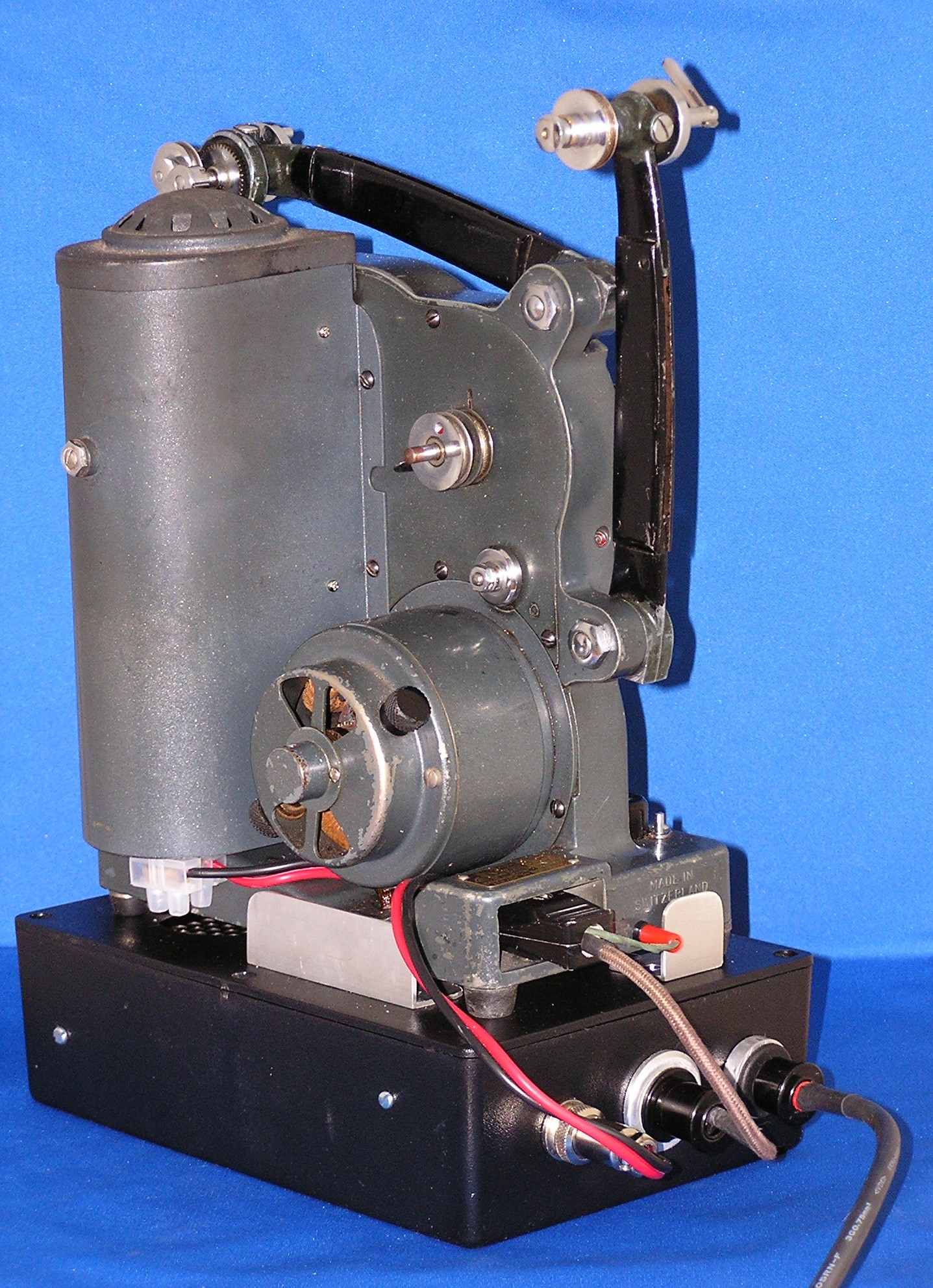
A fair bit of my time has been spent on a lamp conversion for a Bolex DA and putting together a power pack for same, with switches to overcome the tiresome lamp-and-motor-on-as-soon-as-power-on thing. One of the factors here is that, for UK mains, transformers are needed for both the 110v for the motor and whatever the lamp is, in this case 15v 150w dichroic. In my experience, this lamp is about as bright as one can use without damaging the notched titles and still frames, even with the Bolex heat filter. On my machine, I actually had to "de-focus" it a bit to prevent heat damage.
Mikael Barnard found on-line a switched mode power supply that gave 15v 10a (DC, not that it matters) that he wanted me to use to power his new lamp. I noticed that this unit was in fact dual voltage and would work on 240v and 110v. I therefore decided to try out a 110v power pack which would serve for lamp and motor in a fairly compact unit. This approach does, however, need a separate 110v supply of which, of course, those of us who mess about with old projectors have more than enough.
Anyway, a picture is worth a thousand words so here are many words of explanation.


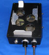

I basically used what I had to hand - the box, various sockets and switches etc. It was a bit of a squeeze getting the power supply into the box, and you will note that even with quite small sockets, I had to use big washers on the outside to leave enough space inside (I did fix some insulation to the end of the power supply by the sockets). As an aside, I did a rough guesstimated costing of the various components used. Even without the power supply (another 15), the total was over 40 at a conservative estimate; a sobering thought. One of the minor costs was a plug and socket to provide an earth - I don't like projectors, even 110v, without an earth. Reading from left to right, the sockets are lamp out, 110v and earth out and 110v in. (The switches are, of course, interlocked so lamp cannot be on without motor, tho' if you have the volume turned down too low on the motor, it may not run even tho' switched on. This matters less for film than for the effect on the motor and the loss of cooling to the lamp. The motor volume control on the Bolex is a sensitive little beast; very little travel lies between overspeed and stop.) I cheated a bit with the connection to the lamp; instead to trying to run a connection thru the body of the machine, maybe making more holes for a socket, I just fitted a bit of plastic connector strip beneath the lamphouse - see last pic.
Anyway, to return; the power unit had a well-ventilated cover, so I felt obliged to make some holes in the top of the box. The perforated cover itself would have been tricky to re-fit, so it just sits in the box on top of the power supply - it hasn't got anywhere it can go. I had always envisaged the power pack as detachable, so the projector was not altered to fit or fixed down in any way. To give extra stability so the machine wouldn't slide off the box, I made some retainers. They had to be reasonably tall because of the projector feet (which of course were virtually useless and had to be replaced) and also the height adjustment at the front, and anyway, that was the size of aluminium angle I happened to have. They are sized to fit the space available - the front one just fits between the front feet.
One peculiar thing had me foxed. the power supply didn't work. Fortunately, Mikael's PPT colleagues had met and overcome this problem. At the right hand end of pic 1, you can see a bit of plastic connecting strip, with what looks like a disc capacitor wired across it. This had to be retro-fitted and is directly in circuit with the negative side (remember, we are talking DC here), tho' I do not know if this is critical or if the pos side would work too. It is in fact a thermistor, in this case one of 20 ohms, tho' the significance of that I do not know. It is a device, I am told, that provides a high resistance to current at first, reducing as it warms up from the current that flows thru. It seems the power supply balks at taking all 10 amps all at once and has to be broken in gently. Anyway, it works so let us not knock it. There is, however, a brief delay between turning on the switch and light appearing.
---------------------------------------------------------------
Going back to my power pack for a Bolex DA. I left the story where I had had, on advice, fitted a thermistor to make the switched-mode power supply work. Now, in accordance with my usual practice, I had wired things so that the lamp switch turned the mains supply to the power pack on and off, rather than switching the much higher lamp current. However, the thermistor had to go into the circuit between the power pack and the lamp, and (you are probably way ahead of me here) the thermistor did not like it and got very hot and tried to melt stuff. Even 3 in parallel couldn't hack it. I had also somewhat misunderstood what I had been told. It appears the issue is that the power pack needs at least some resistance to its output before it will fire up, but a cold lamp has little or none. The solution was to use a centre-off DPDT switch which in one "on" position had the thermistors in circuit, whilst in the other they were cut out of the circuit. Just a couple of seconds in the first position is enough to fire it up without giving the thermistors time to overheat before they are switched out of circuit. Once the lamp is at all warm, the thermistors are not needed at all and one can go direct to the second, "run" position. This means the momentary "off" is not a problem in switching from "start" to "run".
What one really needs, of course, is a good old-fashioned switch that does Off-On-On like one used to find on some projectors. It seems today no such thing can be found - internet just gives me centre-off, even when it claims it's what I want. If anyone has a source, please let me know.
------------------------------------
Bolex Tranny (July 2014)










I am struggling with a Bolex DA. I have a Bolex tranny, that is the size and shape of the normal resistance but weighs a ton. When I connect the two together, I connect, as always an earth, that runs from the projector to the tranny to the mains earth. The problem is that when I switch on, the auto cut-off at the mains trips out. This also happens with other transformers, though, interestingly, not every time. Running the projector without an earth, with its own tranny, the body of the projector registers live with my mains tester screwdriver, which glows red; I measured 126 volts from the machine to the tranny earth (I hope it is nearer 110v under load!). The tranny does not do this, so presumably the problem is with the projector. I have checked all the usual suspects, the brushes, the resistance, the input wires, the reversing switch and removed the lamp so it ent that. I even took the motor out, not a thing I have ever done before, and replaced some bits of wire with rotted insulation, but I have found zilch.
Interestingly, taking the motor out revealed this machine to be one with the larger motor and fan designed to take a 400w lamp, but it is not the 1937 model with the bigger shutter and the curved top to the main body of the mech. The additional fan-power takes the form of a second set of blades on the same shaft, with a sort of collar between the motor and the mech. This collar is about 2cm deep, standing the motor off from the mech body, and surrounds the outer fan except where air needs to flow to the lamphouse. Seems quite a neat adaptation to me. The inner fan is presumably the same as ever it was.
Getting the motor back in was a bugger. The hole the (four) motor wires have to pass thru is immediately below the motor, and I found it impossible to fiddle the motor and ran and collar back into place. In the end, I had to resort to brute strength and ignorance, and took a file to the hole and made it much bigger. I'm not proud of it, but it ent really visible.
But the original problem is still there.
November 2015
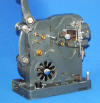
I said earlier I would come back to the early Bolex Model C. I think the one I showed you at the top of Page 1 (borrowed from the PPT) is the earliest I have seen, because it has no reversing and, presumably, no power rewind. Here it is again.
I have since acquired one of my own. This has a weird, mottled finish and is basically much the same as a DA, but without the notching capability. It is definitely dual-gauge - I have the parts. I thought I should try to get it running. Hah! The motor was jammed, and only improved somewhat with lube. When I opened it up I found the cause - the motor has a Mazac frame and is cracking and distorting. This is pretty much incurable, and I am fairly confident the motor has burned out as a result of jamming anyway. I also have a much later Model C, which I have been using as a spares machine, and the motor actually fits, but I cannot get the verdammten thing to give even so much as a twitch. Very frustrating.


[Pic 2 shows the 16mm sprocket and gate, the 9.5 ones being on the machine in the general view at pic 1. The spoolarm converters for 9.5 are in pic 2; they just fit over the 16mm spool noses and only push on until the outer end of the square section of the 16mm spool nose is flush with the surface on which the 9.5 pins are fitted. This ensures the narrower 9.5 spool is still held fairly firmly. The Mazac damage to the motor is in pix 4 and 5; the motor was solidly built into the casing in pic 6 with various fixing screws and with fitted oil tubes to the bearings at each end of the motor - part of one can be seen in pic4]
I found I had opened up a bit of a can of worms. Next thing I did was to test the donor motor on its original machine, which I did by just attaching the wires, not by re-installing the motor. There is a good reason for this. The four wires from the motor, in their aged, oil-impregnated, highly inflexible sleeving have to pass thu a hole below the machine itself with a gap of less than half an inch between motor casing and projector base. The motor has to be installed slowly, pulling the wires thru a bit at a time, whilst balancing the need to fit the fan at the opposite end. I have had problems with this before. The risk of permanently damaging the wires seems considerable.
I am sure I do not need to tell you that the motor worked fine; I should have carried out this test before I started. I now face the problem of tracking the fault thru the even older and more decrepit wiring of the old machine, or adopting a radical solution with a heart and lung transplant of the speed control resistance mat, the direction-changing switch, lampswitch and the associated wiring. I should mention here that one of the screws holding the resistance mat in the base of the old machine would not shift. In the end I had to drill it out and re-tap the hole, as the thread inevitably got damaged - I needed to do this anyway to check what lay beneath.
This all seemed like a lot of work for a machine that would still look pretty rubbish at the end of it all, as age, rust and heat (in the case of the lamphouse) has made a real mess of the paint finish even - and here is the main point - even if the finish was actually meant to look like scales on snake or lizard skin. The size of the "scales" varies so much I begin to wonder if in fact this was not some obscure fault of the paint shrinking, especially as I can see no real sign of any coating remaining between the scales. If the finish is original, is it worth the bother of making the machine work; if not, is it worth the bother of re-painting? The machine seems very early, with a few unique and interesting features. The lamphouse is many-sided rather than round, and there is a nickel-plated cover beneath the direction-change switch. But the original motor is kaput and the snake-finish cover of the original motor will not fit over the donor motor and anyway, much of the uniqueness lies in the paint finish. And it's a Model C - two gauges but no notching, just a still picture device and a centrifugal heat filter.


[The lamphouse, pic 1, shows clear signs of the use of too powerful a lamp. The "skirt" was missing from the earlier PPT machine; this is not surprising as the lamphouse pivots on a removeable rod (as per 200B Plus gate - you can just see the tail of it) thru lugs on the side of the lamphouse and the machine back plate (pic 2). Thiers is also a spring clip on the back plate to hold the lamphouse in place. The problem is that when the spring clip is released, the lamphouse is free to pivot and the skirt promply bangs into the flimsy skirt and damages it. Pic 3 shows the basic casting of my earlier and later machines is the same and, interestingly, there is a brass gear where the later one had paxolin; pic 4 illustrates the centrifugal mech over which fits the heat shutter, here seen sat (upside down) on the normal shutter. Pic 5 reveals why there is a metal plate where the direction change swirch is fitted. As you can see, there is a second, surplus hole intersecting the one for the direction control; I assume this is a relic of the very early PPT version which had just a switch and no direction control. Pic 6 contasts two very different fans, a basic early one and a more turbine-like later model. And finally, the basic simplicity of the direction change mech is shown in pic 7. The earlier one has moulded-in spacers for the three fixing screws, the later one uses separate little spacers.


Some time ago I had some replacement gears cut (in brass) for pre-1937 Bolex DAs (ist pic) and am now contemplating the same for 1937 onwards machines (pic 2). The issue is of course fibre gears - these two are thin and prone to stripping some teeth. I can never accurately count the number of teeth, so hit on this method using an Adobe-type drawing programme.
On a matter that will turn out to be related, I spent an enjoyable few hours one morning wandering about Leighton Buzzard and visiting various engineering establishments. I was well surprised at how many there were and the expensive automated machinery I saw - the town seems to have far more than its share of engineering capability. What it doesn't have, however, is gear-cutting capability, which is what I was looking for. It appears that a) gear-cutting is a highly complex and specialised task, which requires special equipment if you're going to do much of it and b) in consequence of a), gear-cutting has become the province of a few specialist companies who can do it easier and cheaper and are thus used by most companies as a better option than maintaining their own capability in this area. What I was looking to do was to have some gears made to replace the paxolin gear in the post-1937 Bolex DA (I already had some done a few years ago for the pre-1937 model), that tends to strip its teeth after the first 75 years or so. We shall see if I can find another way.
I tried one of these specialist firms for a quote, but it was, as ever, far too costly to be worthwhile - around £100 for a single gear/shaft. After much head-scratching and discussion with very helpful staff at the gear company, an alternative idea emerged. Although they did not manufacture an exactly identical gear, they did have one almost identical. It had no boss, was thicker than needed and of course there was no integral shaft. It was also slightly oversize. Nonetheless, I reckoned it was worth a try to see if my limited engineering skills could do the job. The cheapest material would be steel, but one thing I had picked up in my various discussions up to this point was that there were basically two reasons for the use of Paxolin/fibre (which is what the original was) in a gear train. One was noise, but the other, possibly more significant reason was as a "sacrificial" gear, that would break first before anything more important was damaged. For this latter reason, I opted for the next cheapest option of nylon (Deldrin) and purchased a couple of gears. What I then had to do was to reduce the thickness of the gear whilst leaving a central boss to match the original, make a new shaft and trim just a smidgin from the diameter. Having done this in my rough and ready way, I found, somewhat to my surprise, that it actually worked quite well. Having been successful thus far, I felt emboldened to smash up a broken original gear to extract the shaft, re-use of which would reduce the work involved. I reckon this reduces the cost to around £35/£40, which is considerably more palatable.
February 2018
I have been experimenting with converting a Bolex DA to one of those High Intensity Discharge (HID) lamps like wot Tony Saffrey added to his Specto. The idea was to bring the projection of notched films up to a decent standard as, even converted to Tungsten Halogen (TH), the DA's light is not good enough for a decent size of screen/audience. As I have already converted several DA's to TH, and as there is an HID lamp that will fit the same lampholder, the first part was a no-brainer. Just for info, here are pix of a conversion.


Pic one shows the components. Basically, all traces of the old lampholder are removed. The base-plate, which forms the bottom of the lamphouse and is shaped accordingly, is secured by two oddly-located screws. With these removed, a couple of additional holes are made, counter-sunk from the underside of the plate. This permits the addition of the two nuts and bolts seen here (I used half-nuts as they are thinner). Once the base-plate is screwed back into place, the bolts plus a flat strip secure the main fitment in place.
The main fitment is just a strip of aluminium bent at the appropriate place. The hole at the top needs to be fairly accurately placed to secure vertical alignment, tho' precise placement of the holes for the grippers leaves a bit of scope for adjustment, or one could put a plate under the foot of the main fitment. The foot has large square holes to give a good range of lateral and to and fro adjustment both at the same time. Pic 2 shows the whole assembly. There are a few left-overs from earlier uses (waste not, want not) and I get the vertical section away on each side to help air flow.
Precise adjustment is going to be just trial and error, as the old trick of applying a low voltage to a TH lamp and adjusting by hand and eye with the lamp on is not safe for HID, because of voltages and the considerable UV emissions.
There was always going to be a snag, of course. Although on test the light output seemed good, as expected, there was a tendency to burn the film; not immediately, but soon enough to risk long-term damage to the film unless additional measures were taken. This is where it got complicated.
The basic problem is that a) there is very little spare room inside the DA mech and b) the heat filter must synchronise with the stopping of the mech for the notch. An alternative approach might be to put a permanent piece of heat-stopping glass inside the lamphouse, but this would reduce light output at all times, not just for titles. I decided therefore to try adding an additional layer of mesh to the existing heat filter. This involves something I have not done before, ie removing the re-set knob for the notching mech as this is directly coupled to the heat filter.


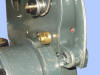
In pic 1, you can see the original filter is held, round only part of its circumference, by 3 small screws which pass thru a retaining strip, then the mesh, then into threaded holes. I was a tad reluctant to take all these screws out, as I feared the whole lot would just disintegrate in my hands. So I cheated by making two new holes, as seen in pix 2 and 3. Part of the aim of doing this was to keep a small air gap between the different layers in the hope this would slow any build-up of transmitted heat. Pic 4 shows the whole thing in situ.
My original thought was that I could get away without a dowser, simply by opening the little door behing the lens and re-directing the light from the lamp to the rear of the machine. After a little more thought, I decided against this as it is quite easy to knock the little door shut while re-threading, and also because of the UV warnings on the lamps.
So I decided to fit a dowser, although this involved rather more mods to the machine than I was 100% happy with.


Here is what I came up with. Two guide strips are screwed to the mech side plate from the inside (with counter-sunk holes as the shutter is very close), to take a vertical lock-gate-paddle sort of affair. I had to reduce the lip on the straight edge of the lamphouse top to make room for the handle. Another nut and blot near the top of the projector serves as a travel-limiter for the sliding plate. Down is off for obvious emergency/safety reasons.
Testing must now follow - re-assembly has been awaiting taking these pix for you, but I will report the results later.
(Later)
You will recall I told you about my attempts to fit an HID lamp to a Bolex DA. I was using the lamp with the integral mirror, which needs to have 32mm from the plane of the film to the front edge of the mirror. There is unfortunately no way this can be achieved with the DA and the results were no better than from a normal tungsten halogen lamp.
This is the report I wrote to the projector owner on the alternative solution of fitting a tungsten halogen lamp in place of a disappointing attempt to fit an HID-150 mirror lamp to a post-37 DA. This was, of course, done before the idea of the HID-type route had really taken hold in my slow brain.
"Have done the QI conversion on the other DA. As usual, there was a long string of things actually to do that are not apparent at first sight. Even before I really started, I had to lever off the double pulley on the back that drives the take-up and rewind belts, which had seized itself solid to the shaft. I sanded the shaft down a bit to re-fit. I discovered on final testing that there was not a lot of point, as it appears that you do not have a working reverse setting. I had a quick look at the switch, but there was nothing obviously wrong, which meant the fault was probably inside the switch or even perhaps in the motor wiring. I felt discretion was the better part of valour here as you don’t use it anyway.
Now on to the meat of what I needed to do.
1. Strip out internals of lamphouse cover. So the condenser lens housing, held in by those tiny screws on the side (one always sticks), has to go, and then nuts have to be fitted to the tiny screws to avoid light leakage. Ditto mirror mounting at the back, only a bigger screw, and similar for the inner lamp sleeve, which attaches to the lamphouse top.
2. Once inside, there’s the actual lamp holder. To disconnect the wires, you have to remove the plastic insert holding the actual lamp socket from the steel cylinder it is mounted in. Only it does a sort of plastic Mazac thing and won’t budge without much brute force (hammer and large wooden dowel), so the socket got well bashed. I didn’t want to cut the wires, which I have left in place in the base, terminated in a connecting strip to keep them out of the way.
3. Then we have to measure out and make up a bracket that can hold the lamp at the right height with a bit of fore and aft adjustment to get best light without burning the film and fix metal strips to hold the lamp, plus make a fairly round hole for the light to go through. This lamp is a “force” fit into the slot that takes the raised bit on the front edge of the mirror. You may need to do a bit of re-bending of strips if you ever have to fit a new lamp. Looking thru from the front without the lens in place gives a good view of the lamp for centralising. When it comes to fixing the holder in place, note it does matter which way up you put the metal strip under the hexagons.
4. The base plate had to come off to sort the wires. One of the screws was rusted solid and had to be drilled out, which buggered the socket, so I had to apply some of that hard-setting putty and make a new thread. Do not tighten screws too tight! I sanded the base plate to get rid of the worst of the rust and gave it a couple of coats of acrylic. Not perfect but better. The rubber feet had almost vanished above “surface” level so I tried an experiment. In the past, I have used the full height of replacement feet, and then found it stopped the machine fitting in the wooden box – lid wouldn’t close (not that you have a box in this case). This time I cropped the feet to give a racy low profile.
5. Then the wires from the lamp were just too short to reach direct to the input connector strip below the floor of the lamphouse, so I had to fit a second connector strip inside and fit linking wires. Nothing can ever be simple.
6. All you need now is a 15v 150w power supply. These are available on the internet, and usually will take either 110v or 240v input without adjustment. Unfortunately, these are “switched mode”, not normal trannies, and will not power a lamp from cold without a kick-start. This takes the form of a thermistor in circuit for cold start, to be switched out almost instantly to avoid overheating, leaving the lamp in direct circuit as soon as it starts up. I do this by way of a centre-off switch (“on-off-on”), with the thermistor in circuit for the “up” position, then a quick shove across the centre “off” to the lower “on”, which is direct feed (although I wonder, thinking about it, if an “(on)-off-on” wouldn’t be better, with the spring-loaded momentary (on) preventing any risk of melting the thermistors. See final comment in (5) above.
You may be lucky enough to find a tranny instead, but they are rare. The 24v type of tranny is slightly more common but such a lamp would have little or no chance of avoiding burning the film. More details about using a switched mode power supply are at page 3 above. Or you could go with a 12v 100w lamp, power supplies for which are much easier to find. You could even use the defective reverse as a motor on-off switch, with the 12v supply separately switched, as a full interlock is not really needed here. What a pity that the need to accurately place the HID lamp at 32mm from the plane of the film meant we couldn’t use one to any great effect, tho’ I have yet to pursue using one of the peanut type with the existing condenser etc set-up. Have heard no more about LED’s either.
Final testing showed a full 30 seconds of still frame without any sign of heat damage to the film, tho’ you will obviously wish to do your own testing as well."
You may well understand that by the time I had finished writing this, I was seriously beginning to wonder if the best way to convert a Bolex DA/PA might lie in the peanut equivalent of the HID lamp, an NSD-150. So I promptly tried this, using as a test bed a pre-37 machine (a PA, in fact) simply by putting a metal bar with a snug fit into the original lamp socket and mounting the HID lamp socket to that. Height is not too critical as there is plenty of adjustment up and down with the original holder, and centring takes care of itself. There is also some fore and aft movement from the mounting plate for the original.
I made quite an elaborate douser arrangement when I converted the DA above, but decided to go simpler this time. Here is a pic.
Working from left to right we have the douser plate, with folded sides that wrap round the condenser lens housing and help keep the plate in place. A brass rod serves to make the step across from the position of the condenser lens to the centre line of the lamphouse. The centre of the lamphouse cap is drilled out, starting from the hole where the inner lamp sleeve was fitted. I tapped the hole in the lamphouse cap to M3, then made a brass sleeve piece with a 1.5mm bore for the activating rod and an M3 thread to screw it into place. The plastic knob is a late addition when I found the original metal knob I fitted got too hot. It seems to work ok, tho' I am wondering if the metal plate of the douser is not a bit flimsy. Time will tell. What I can tell you is the new lamp gives a good, white light, significantly brighter than a tunsten halogen lamp. There are no visible signs on the screen of over-heating of the film after a full 30 seconds. I am putting the difference from the reflector lamp discussed above down to factors such as the intervening condenser lens obviating the need for additional heat filtering.
A big advantage of the HID type of lamp is the small size of the necessary power pack, which would fit easily inside the kind of base box described on page 3 above. This bulb could provide a solution for other projectors where it is not possible to achieve that 32mm film to lamp distance that is essential for the HID-150 mirror lamp. And it looks to be a much simpler conversion.....
The bad news is that both the HID mirror lamp and the equivalent peanut bulb may disappear from the market because of new rules - they seem to contain mercury or summat, and neither manufacture nor disposal is environmentally friendly.
------------------------------------------------------------------------------------------------------------------------------------------------------
Discovered the other day an odd little quirk of the Bolex whixh I had not encountered before. As machines get older, I thought it might be sensible to record it here.
This is a rather badly-drawn exploded picture of the double pulley on the rear of a Bolex DA that drives the take-up and the rewind belts. The actual pulley as seen is also shown.

The turquoise section is held firmly to the central shaft providing the drive by a grubscrew in the hole marked. Each of the side pieces has a central bore that is able to pass over the lip on its respective side to rest up against the side of the centre section of the turquoise bit when properly assembled – see photo.
This is where it gets complicated. The “trough” between the side lips and the central section of the turquoise bit is grooved around its perimeter to a gradually increasing extent until it reaches a maximum depth, at which point there is a step. This is basically a form of ratchet. The slider goes into the grubscrew hole in the pulley, followed by a spring, then finally the grubscrew itself. When the turquoise bit rotates, the slider goes round the perimeter of the “trough” until it stops because the spring has driven it into the deepest part of the groove and the turquoise section then drives the pulley. If rotation is in the opposite direction, the slider enters the groove from the deep end, pushed in by the spring and gradually emerging from the groove against the pressure of the spring as rotation continues. There is then no drive to the pulley. This action of the slider is also what stops the pulley part just falling off.
However, the really difficult part of all this is that none of the slider, spring or grubscrew, shown enlarged under the drawing of the pulley, is more than about one eighth of an inch in length and even less in diameter.
I got into this digression because when I was attempting to show a notched film to a friend a while ago, the film embarrassingly would not take up. I suspect that over time, the spring has lost its springiness and was no longer doing its job. I ended up making a non-springy thing to replace the actual spring, which served to lock the take-up pulley so there was no ratchet action. The only purpose this serves anyway is rewinding, which I tend not to do on projectors that are already worn enough as it is. I don’t have any springs that tiny anyway.